ASME FEA for Pressure Vessels and Process Equipment
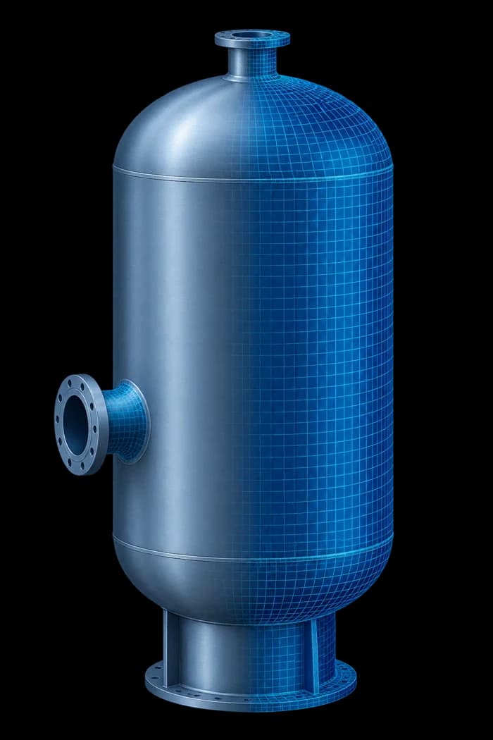
Graphler Technology Solutions provides finite element analysis for pressure vessels, storage vessels, nozzles, heat exchangers and associated process equipment. We evaluate critical regions, interpret stresses against applicable design criteria, and support practical improvements to geometry, reinforcement and supports. Our services include Design by Analysis using ASME Section VIII, Division 2, Part 5, where applicable. Each assessment follows the governing equipment code, specified edition, operating conditions and agreed analysis scope.
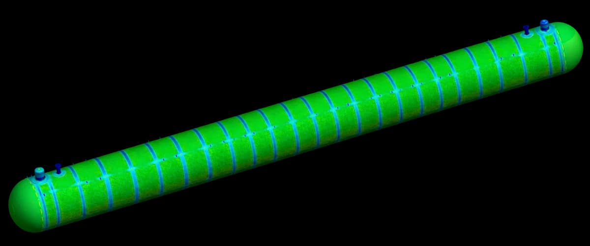
Engineering Decisions
Support Engineering Decisions Before Fabrication
Identify critical locations
Understand how pressure, temperature, external loads and support conditions affect shells, heads, openings, connections and attachments.
Evaluate design improvements
Assess changes to thickness, reinforcement, geometry and support arrangements with consideration for fabrication and assembly.
Document the assessment clearly
Connect modelling assumptions, load combinations and calculated results with the applicable acceptance criteria.


Equipment Applications
Equipment We Analyse
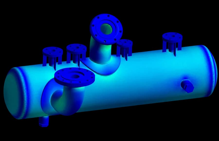
Pressure Vessels
Structural assessment of horizontal and vertical vessels, separators, receivers, columns and other pressure-containing equipment.
We examine shells, heads, transitions, openings and support connections under internal pressure, external pressure, operating weight and specified mechanical loads. Local assessments help resolve details that require more detailed evaluation than standard design calculations provide
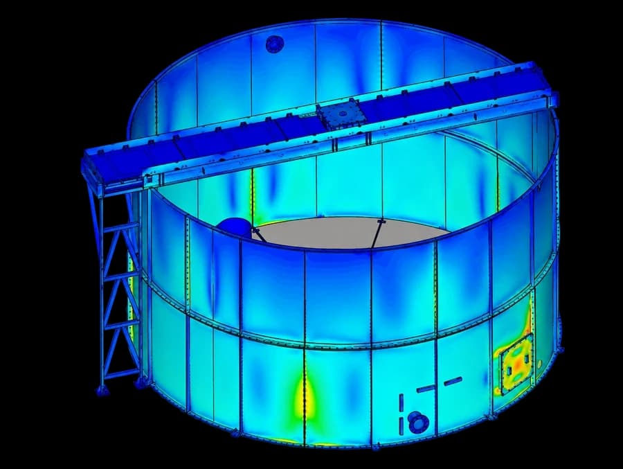
Storage Tanks and Pressurised Storage Vessels
Analysis of pressurised storage vessels, LPG bullets, mounded vessels and atmospheric storage tanks. Assessments can address liquid loading, external pressure, support interaction, settlement, wind, seismic effects and local attachment loads. Pressurised vessels follow the applicable pressure-vessel code; atmospheric tank assessments follow the relevant tank standard, such as API 650
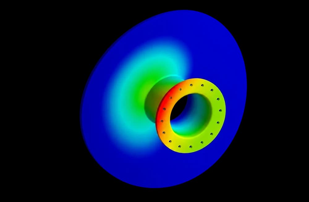
Nozzles and Reinforced Openings
Local stress assessment of nozzle-to-shell and nozzle-to-head junctions under pressure, piping forces and moments. We evaluate nozzle necks, reinforcement pads, insert plates and surrounding vessel regions. Where required, alternative reinforcement arrangements are compared to understand their effect on local stresses and load transfer
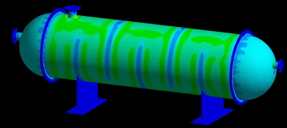
Heat Exchangers
Structural and thermal assessment of shell-and-tube heat exchangers and their pressure-containing components. Analysis can include shells, channels, covers, tubesheets, nozzles, flanges and supports. We assess pressure combinations, temperature gradients and differential expansion, together with lifting, handling and transportation loads where these form part of the scope
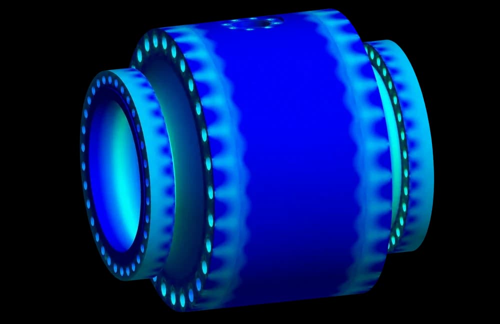
Valve Bodies and Pressure-Containing Assemblies
Assessment of valve bodies, bonnets, covers and other pressure-containing components with complex geometry or contact behaviour. Models can account for internal pressure, hydrotest conditions, bolt preload, component contact and operating forces. Results help identify critical sections and evaluate local changes to the assembly
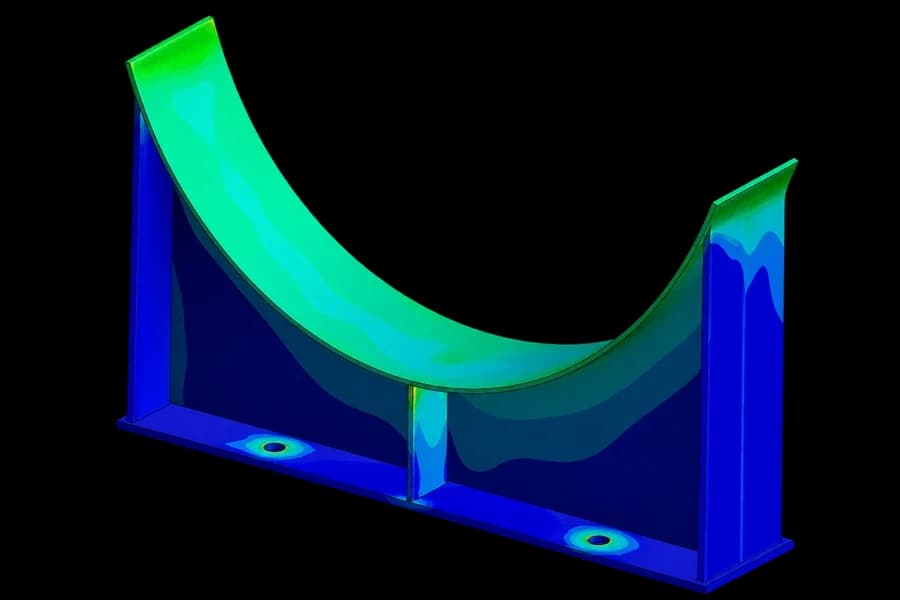
Supports and Equipment Attachments
Assessment of skirts, saddles, brackets, lifting lugs, trunnions and other load-bearing attachments We examine how loads pass through the support and into the equipment wall, including local stresses around attachment welds and changes in stiffness. Operating, wind, seismic, lifting and transportation conditions are considered as applicable
ASME Section VIII · Division 2 · Part 5
Stress Classification Line (SCL) Evaluation
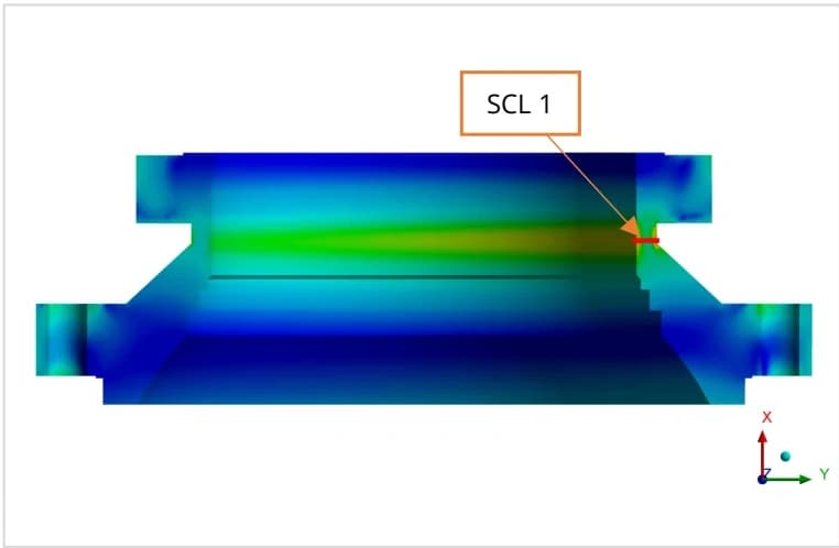
We define Stress Classification Lines through critical wall sections and linearise the stress components to obtain membrane and bending results. Stresses are classified by their source and structural behaviour, including general primary membrane, local primary membrane and primary bending, and evaluated against the applicable ASME Section VIII, Division 2, Part 5 criteria. Each evaluation documents the SCL location, load case, material, calculated stress, allowable limit and assessment outcome, providing a traceable basis for engineering review.
SCL evaluation example
PTPA 48-inch Class 600 ball valve · SCL 1 · Flange 1 LC-01 design pressure: 10.2 MPa · Material: A350 Gr. LF6
Primary Stress Assessment
| STRESS CATEGORY | CALCULATED (MPa) | REPORT LIMIT (MPa) | RESULT |
|---|---|---|---|
| General primary membrane, Pm | 150.09 | 238 | Within limit |
| Primary membrane + primary bending | 265.19 | 357 | Within limit |
Reported assessment: The membrane and membrane-plus-bending stresses at SCL 1 are within the limits adopted for this design load case
View the through-thickness stress breakdown
| COMPONENT | INSIDE | CENTRE | OUTSIDE |
|---|---|---|---|
| Membrane | 150.09 | 150.09 | 150.09 |
| Bending | 210.26 | — | 210.26 |
| Membrane + Bending | 265.19 | 150.09 | 251.30 |
| Peak | 40.621 | 32.376 | 84.985 |
| Total | 252.81 | 148.83 | 322.65 |
Equivalent stress values are reported for each component and are not added arithmetically. The report does not list a separate centre bending value.
Source: PTPA report X012PTP00040926, Revision 00, 07 September 2026, page 18. Basis: ASME Section VIII, Division 2, Part 5. Values and allowable limits apply to this illustrated section and load case.
Assessment Methods
Analysis Capabilities
Stress Linearisation and Classification
Evaluate through-thickness stress distributions at selected locations and interpret the results using the applicable stress categories and limits. Assessments distinguish membrane, bending and local peak behaviour to support meaningful engineering decisions
Pressure and Combined Loading
Assess operating, design and test conditions, including combinations of pressure, weight, piping loads, support reactions and environmental loads.
Thermal–Structural Analysis
Evaluate stresses caused by temperature gradients, differential expansion and restrained thermal movement during steady operation or transient heating and cooling
Buckling and Stability
Assess instability associated with external pressure, vacuum, compression or other relevant loading. The analysis method accounts for the required treatment of geometric imperfections, material behaviour and design margins
Fatigue and Cyclic Loading
Assess the effects of repeated pressure, temperature and mechanical load cycles. Depending on the design basis, the scope may include fatigue screening, detailed fatigue evaluation and ratcheting assessment
Nonlinear Analysis
Represent contact, separation, material plasticity and large deformation where these behaviours influence the assessment. Select the analysis method according to the equipment, loading and failure mode being evaluated
From Requirements to Recommendations
Our Assessment Process
Establish the design basis
Review geometry, materials, temperatures, pressures, load cycles and support conditions. Confirm the governing code, edition, load combinations and required acceptance checks
Develop and verify the model
Prepare the analysis geometry, mesh, connections and boundary conditions. Review mesh sensitivity, load application and solution behaviour
Evaluate the response
Identify critical regions and assess the relevant stress, deformation, stability or cyclic response against the agreed criteria
Refine and document
Evaluate agreed design changes and provide a report connecting the assumptions, results and engineering recommendations
Technical Reporting
Deliverables
A documented assessment, from analysis results to design recommendations

Deliverable 1: Stamped report
Analysis basis, methods, results and conclusions, with sign-off or stamping as agreed

Deliverable 2: Stress contours
Load-case plots identifying critical stress regions across the equipment

Deliverable 3: Deformation plots
Displacement results showing movement, distortion and critical locations

Deliverable 4: SCL evaluation
Stress-classification lines, membrane and bending results, and acceptance tables

Deliverable 5: Design recommendations
Suggested improvements and comparisons of agreed design alternatives
Supporting documentation covers materials, geometry, mesh, boundary conditions and load combinations, with buckling, fatigue or nonlinear results where applicable
Supporting Process Industries
Our services support equipment manufacturers, fabricators, EPC contractors and plant engineering teams working across oil and gas, petrochemicals, chemical processing, power generation and industrial process systems
Discuss Your Pressure Equipment Analysis
Share your equipment drawings or CAD model, material specifications, design pressures and temperatures, external loads and governing code requirements. We will help define an assessment scope suited to your equipment and the engineering decisions you need to make