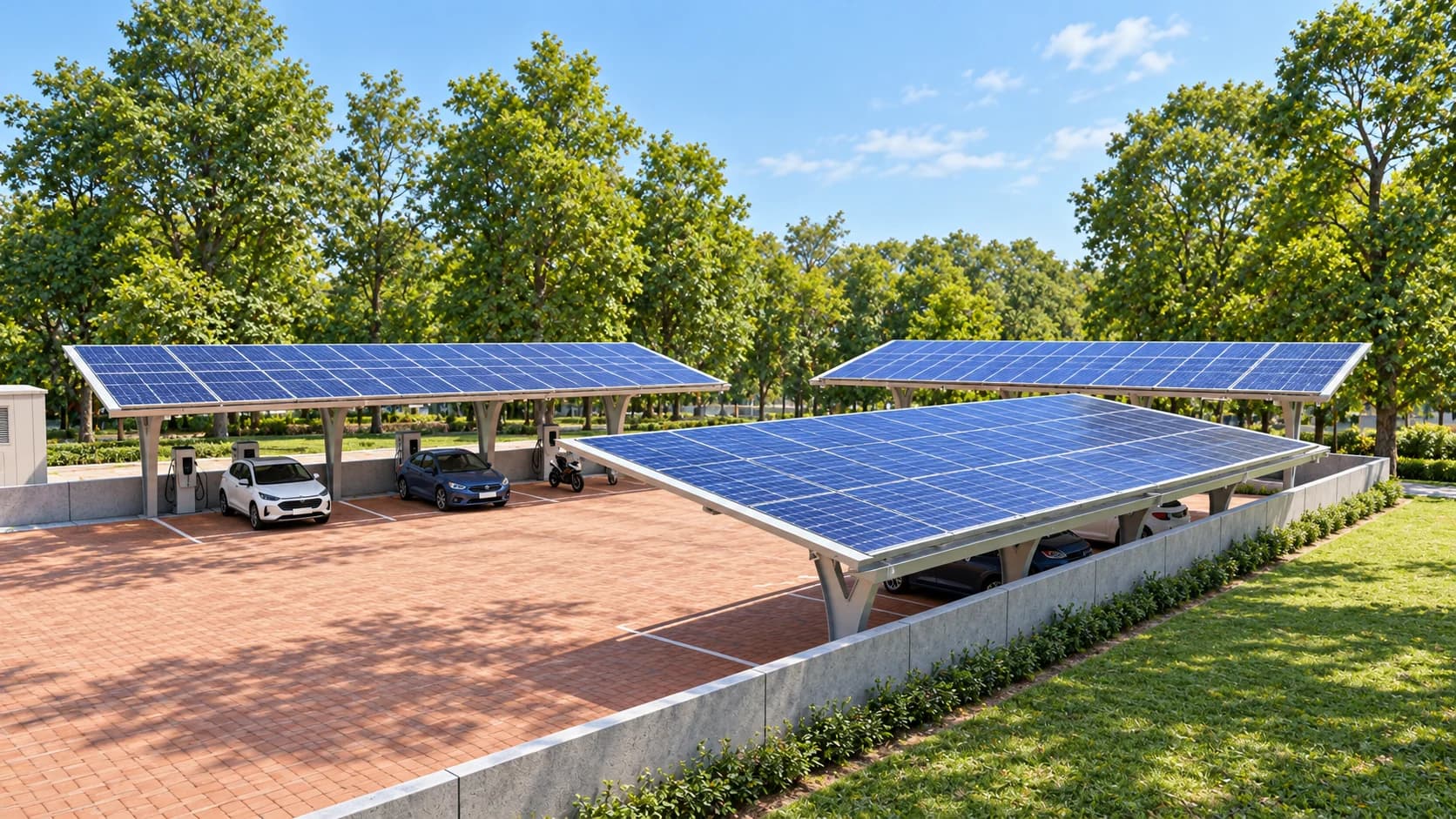
Solar carport design and development
Canopy concepts, modular connections and structural investigation
Mahindra Susten / PDD
Solar Carport Design and Development
- Requirement
Solar generation above usable parking
Develop a module mounting structure that preserves parking access and considers assembly, drainage and maintenance from the outset
- Challenge
Coordinate the canopy and its connections
Resolve the support arrangement, bolted interfaces and module rails while allowing access for cleaning and practical installation
- Deliverables
A product development package
Concept assemblies, connection details, dimensional drawings, digital assembly sequences, structural investigation and site visualisations
01 / Product Brief
Parking, installation and maintenance needs
The brief called for a modular Y-type structure with a central column and cantilever bracing. Construction and maintenance feedback added practical priorities: easier fit-up, manageable members, protected cable routes and a roof arrangement that could collect rainwater
| DESIGN PRIORITY | HOW IT SHAPED THE DEVELOPMENT BRIEF |
|---|---|
| Modular construction | Bolted foundations and member connections, with features to reduce assembly mismatches |
| Module support | Lightweight mounting members coordinated with rails, clamps and cable clips |
| Water management | A central gutter and provision for seals between adjacent modules |
| Service access | Maintenance ladders and provision for module-cleaning equipment |
These are design requirements. The following concepts explore different ways to address them
02 / Concept Exploration
Alternative structures for the solar canopy
We explored the supporting architecture before developing individual connections. The concept sets vary the column arrangement, bracing and roof members. Each view below represents a separate design study
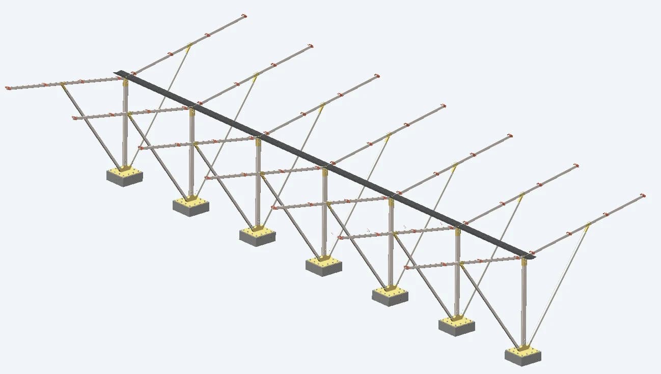
Concept 01 / central supports
A repeated line of central posts carries the two roof wings. Braces connect the cantilever arms back to the columns
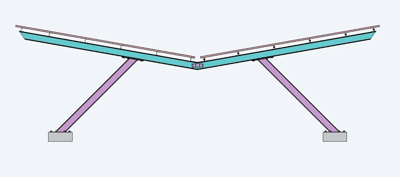
Concept 02 / inclined supports
Inclined legs support a twin-wing roof. The assembly sequence develops this arrangement through the roof rails and modules
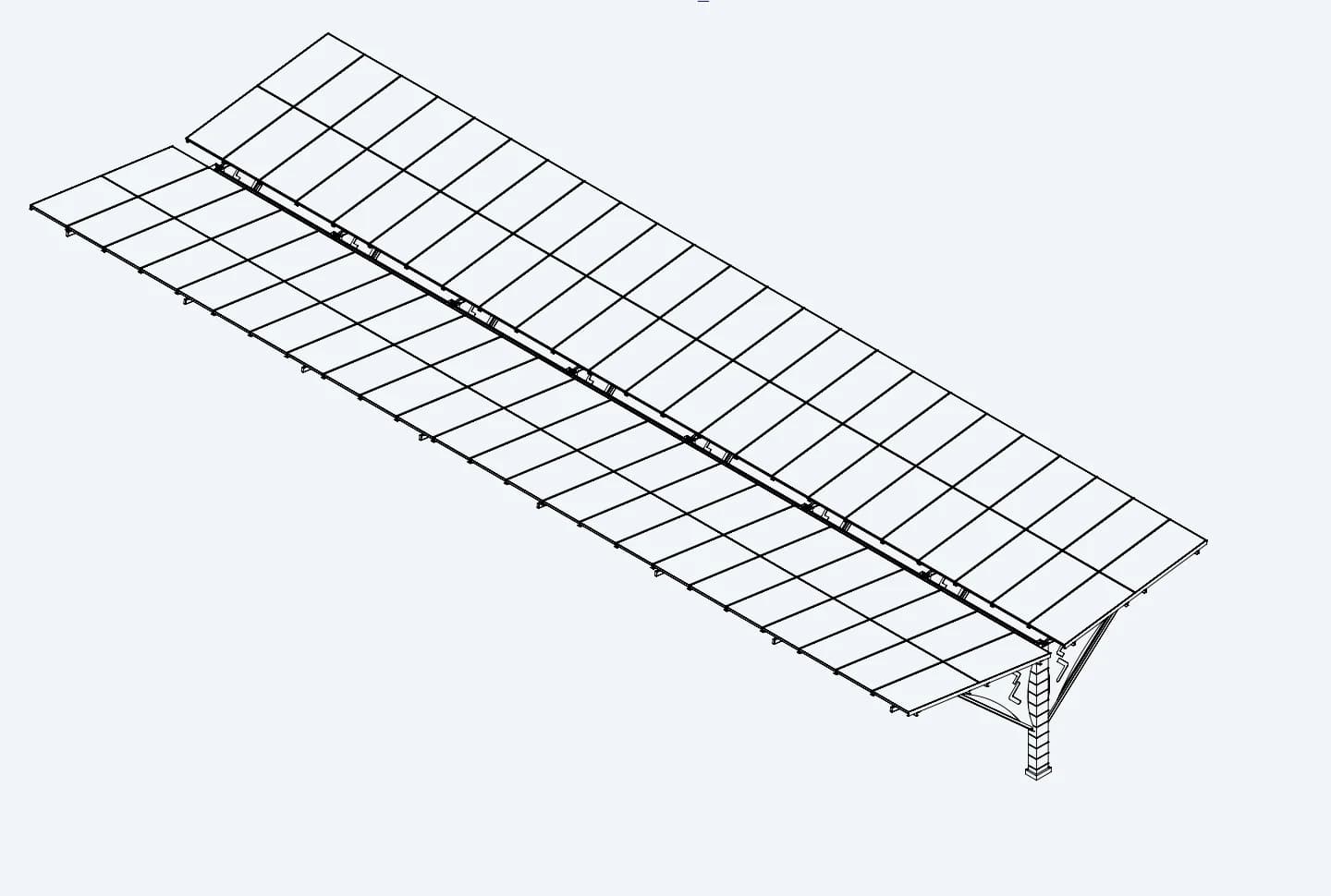
Concept 03 / integrated canopy
A dimensioned concept coordinates the roof grid with central supports, braces and a shaped column covering
03 / Product Architecture
The load path beneath the modules
In Concept 03, module rails sit above purlins and rafters. Braces connect the roof arms to the central column, which transfers the loads to the foundation. The drawing also coordinates a façade around the column and bracing
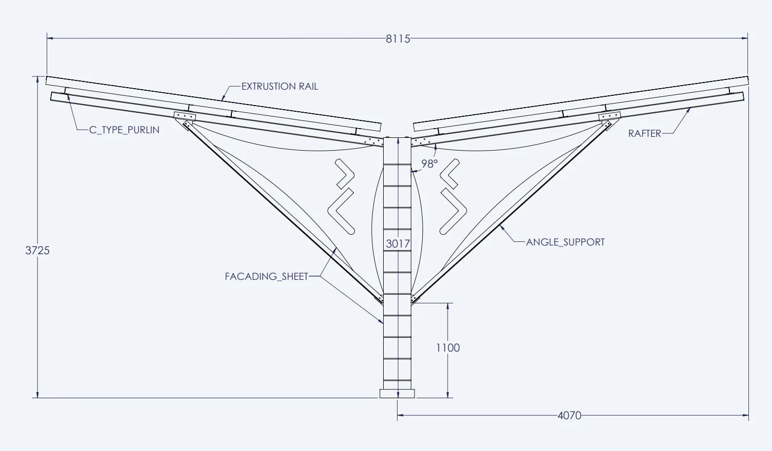
8.115 m
Overall canopy width
3.725 m
Outer canopy edge height
3.017 m
Centre-column top height
04 / CAD Development
A repeatable structure along the parking row
The complete assembly relates the transverse support to the length of the canopy. Repeated supports, longitudinal members and the module grid make the interfaces visible across the whole structure, giving the detail work a common dimensional basis
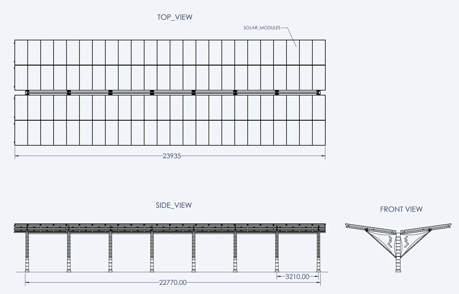
Concept 03 drawing: 23.935 m overall roof length and a 3.210 m indicated support bay. These values do not describe the later site render
05 / Connection Development
Base and column connection details
The connection studies translated the canopy architecture into individual parts. The three-way base casting and two-way column cap define how the structural members meet, with section views and hole locations supporting detail and estimate review
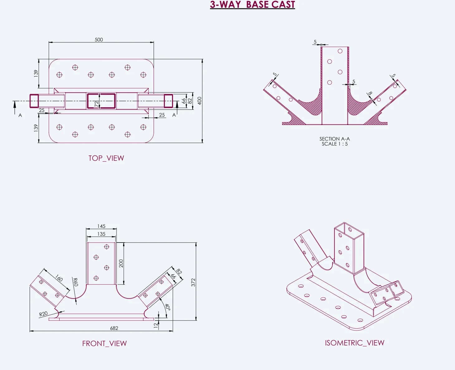
Three-way base casting
The drawing brings the foundation plate and three member interfaces into one component, with views of the plate, holes and local sections
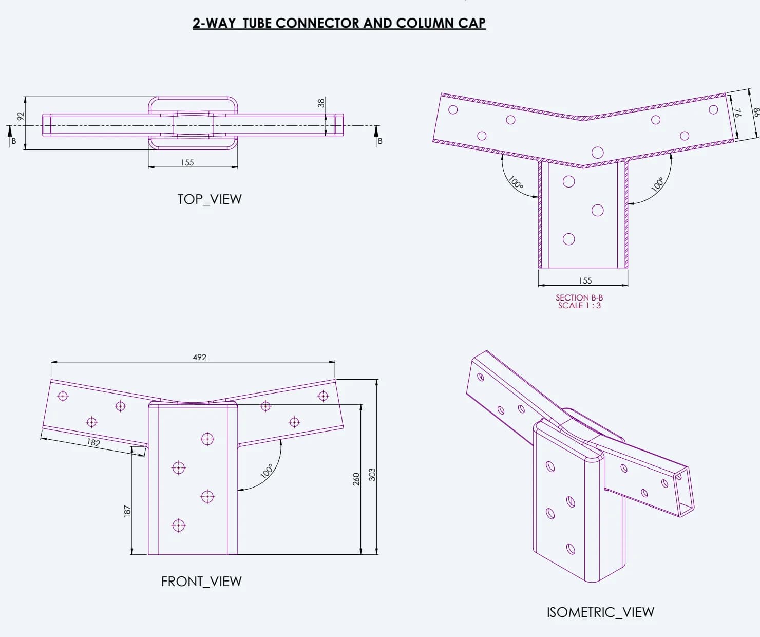
Two-way connector and column cap
The cap locates the two roof arms relative to the central column. Its drawing records the member angles and fastening interfaces
Original development drawings issued for estimate review
06 / Digital Assembly
The structure assembled one interface at a time
The CAD sequence makes the assembly method explicit. It starts at the foundation, progresses through the post and brace connections, and builds out the roof structure. The close views show the order of fit-up and the access needed around each joint.
01 Foundation Interface
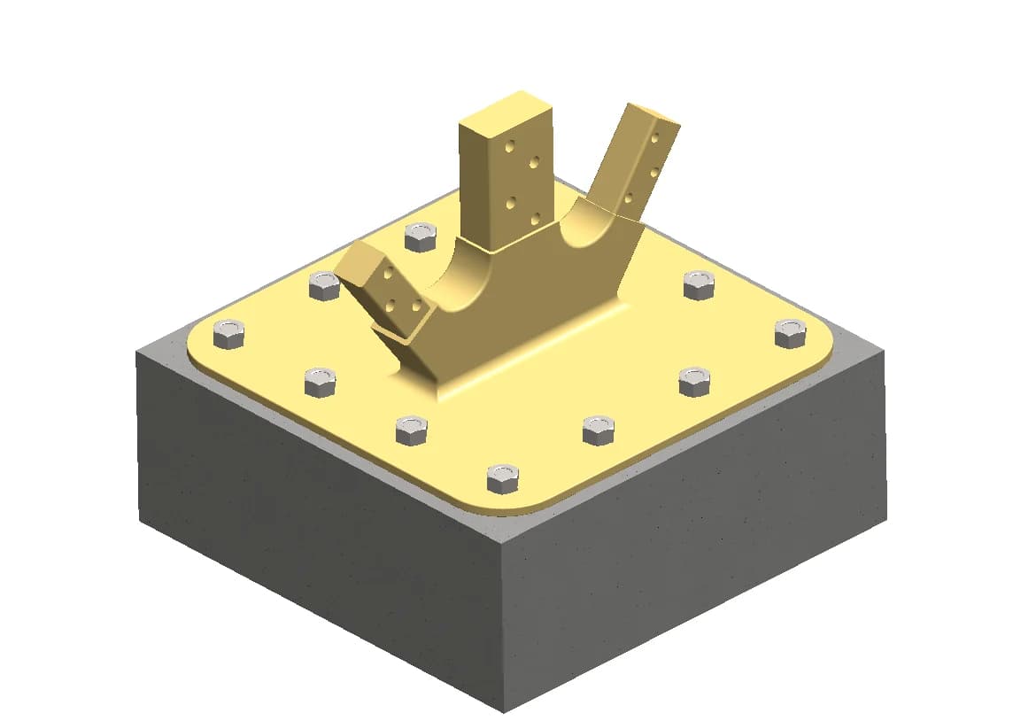
The base component locates the structural members on the foundation and shows the anchor-bolt arrangement
02 Column Head
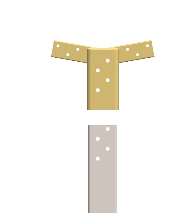
The column-head connection aligns with the vertical post before the roof members enter the assembly
03 Brace-end Connection
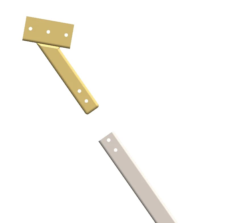
A separate connection piece relates the diagonal brace to its upper attachment
04 Bolted Brace Joint
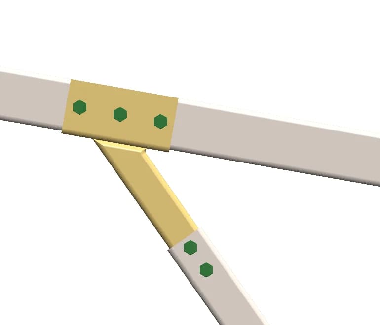
The close view shows the brace meeting the roof member through a bolted connection
05 Repeated Roof Bays
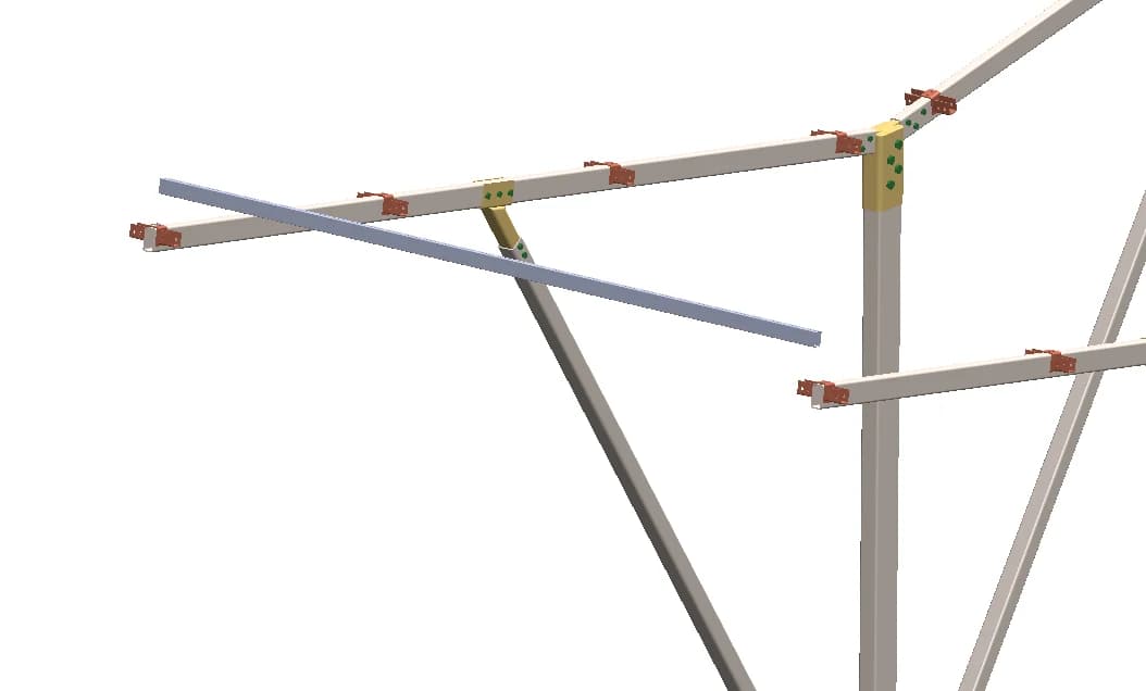
Successive posts and transverse arms establish the support spacing along the canopy
06 Roof Support Grid
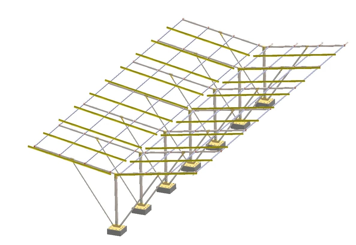
Longitudinal members complete the grid that carries the module mounting structure
Original digital assembly sequence for Concept 01
07 / Modules & Water Management
Detail at the working surface of the canopy
Concept 02 carries the assembly study through to the modules. The views connect the roof grid to panel placement and show the central channel between the two wings. The wider brief also considered module-gap seals, cable routing and access for cleaning
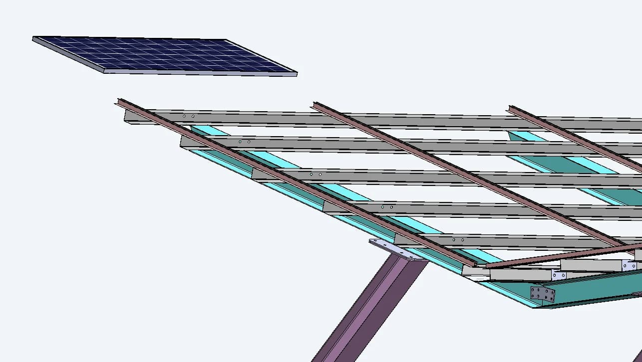
Module installation
A module approaches the supporting rails in the assembly sequence, exposing the roof grid and its attachment arrangement
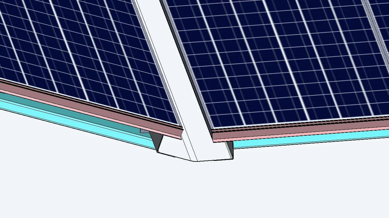
Central drainage channel
The close view shows the gutter between the module fields. Drainage forms part of the canopy layout alongside the structural members
08 / Structural Investigation
Overall bending and local stress behaviour
We used structural simulation during development to examine the central support and canopy arms together. The deformation view shows the bending pattern, while the stress view identifies the upper connection as an area for closer engineering review
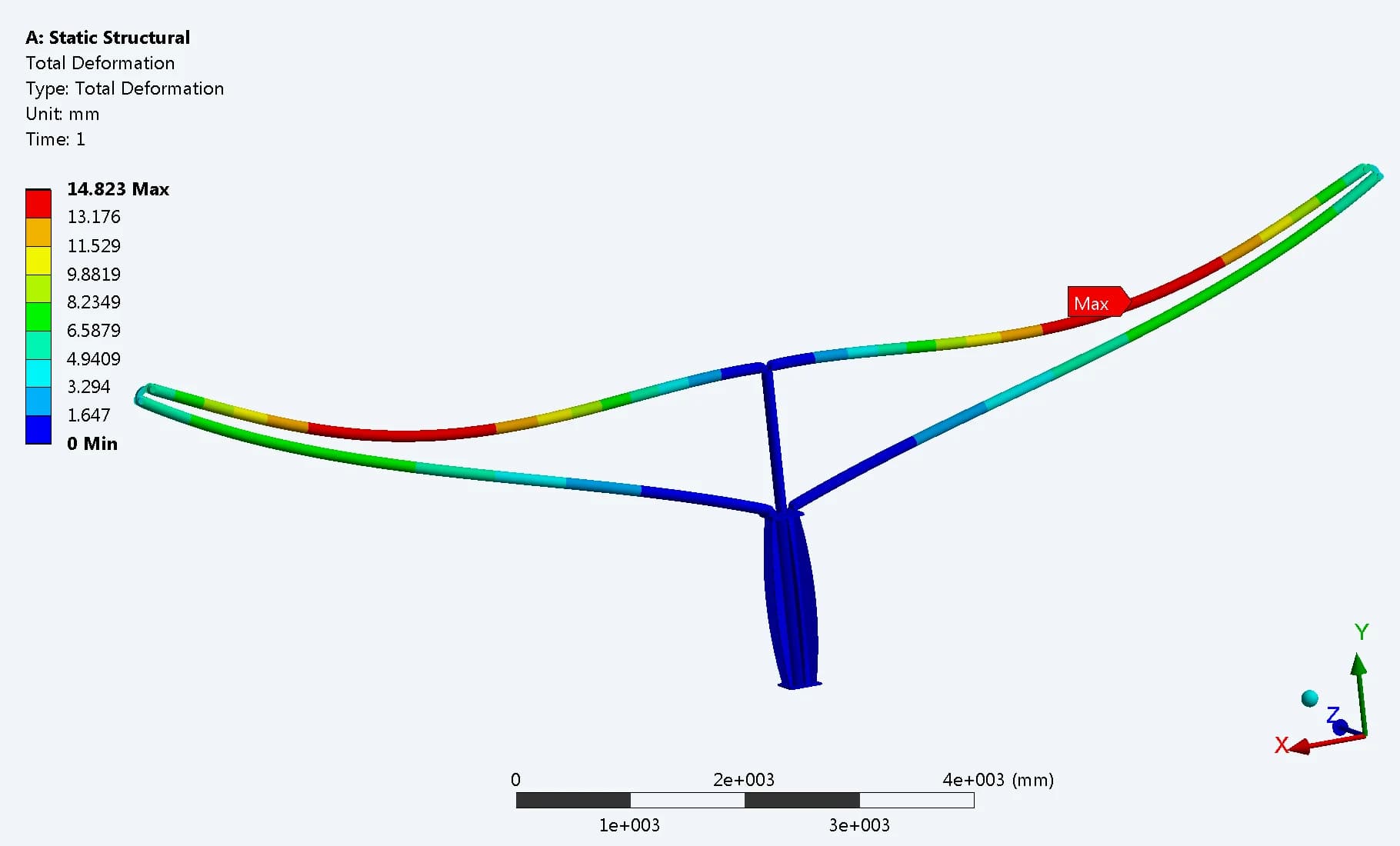
Development-stage deformation
The contour makes the displacement pattern along the canopy arms visible relative to the central support
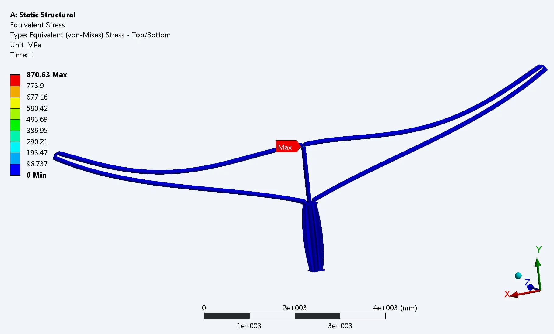
Stress in the support assembly
The full assembly view relates the local stress concentration to the overall post-and-arm arrangement
Original development-stage results. The available plots do not establish a final load rating or structural acceptance.
09 / Critical Connection Review
The upper connector in greater detail
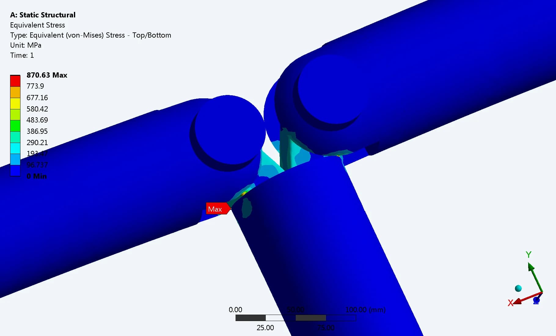
Load transfer through the joint
The assembled view shows the arms meeting the column connector and locates the concentrated stress around that junction
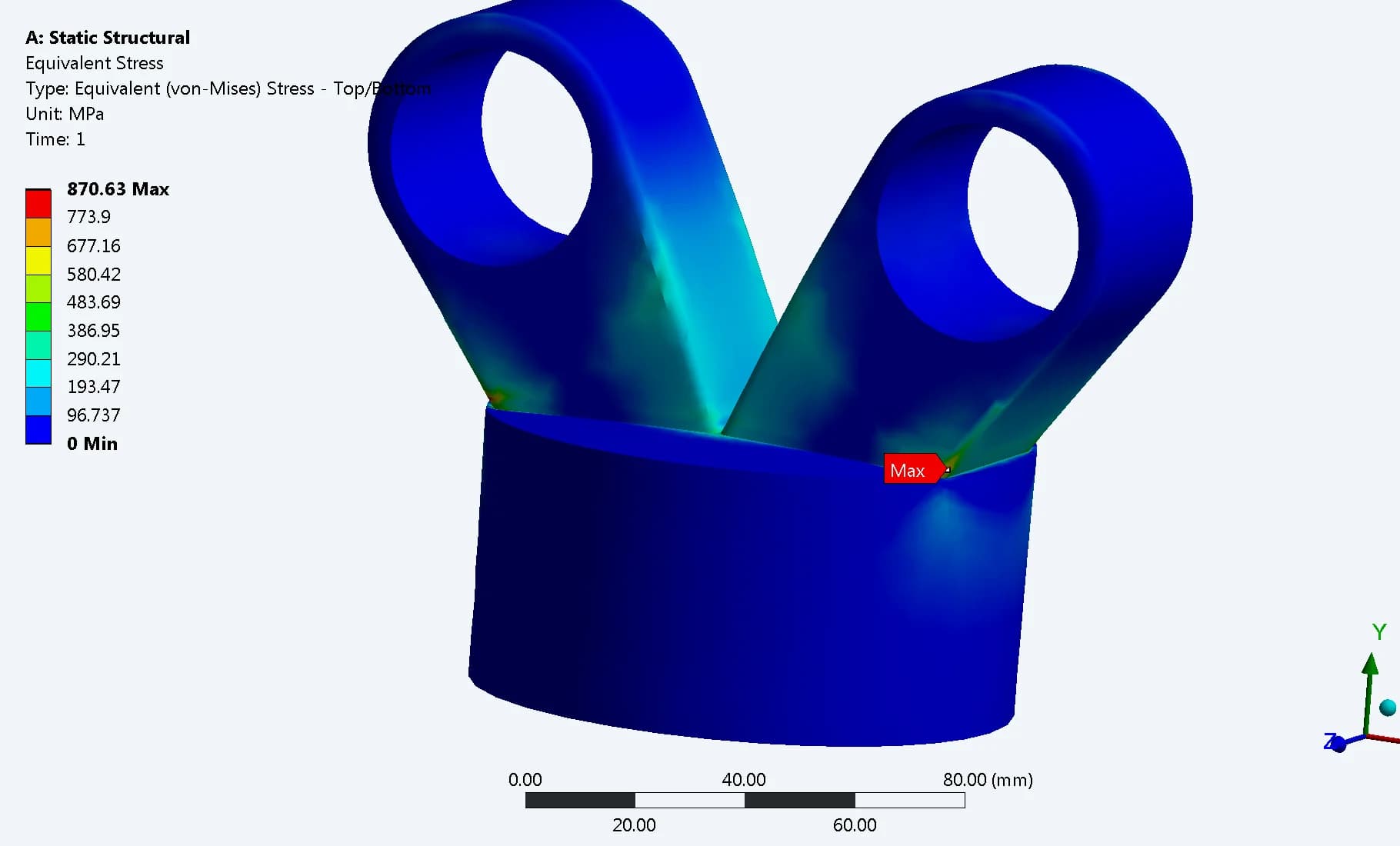
Transitions around the mounting eyes
The component view isolates the two-eye connector so the local stress pattern at the eye-to-base transitions can be examined
The study links the response of the complete support to the detail of a critical connection. These close views show the same analysis result at a different scale, providing material for joint review during development
10 / Site Application
The carport within a wider parking layout
Later project visualisations explored how several canopy rows could sit around a shared parking courtyard. Vehicle circulation, charging locations and supporting equipment brought the product into a site context. This application study is distinct from the earlier concept configurations
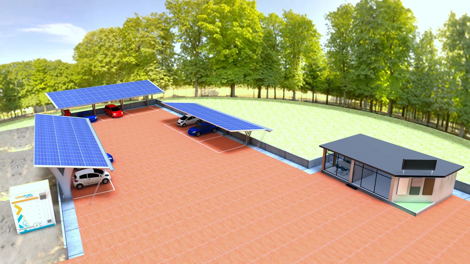
Original GPCL site visualisation. Rendered vehicles and equipment communicate the proposed arrangement.
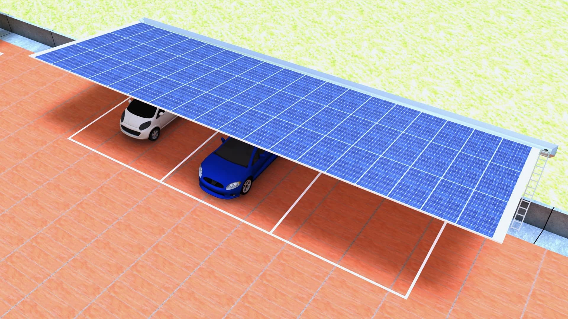
Module field and parking bays
The elevated view relates the roof footprint to marked parking spaces and the repeated support positions below
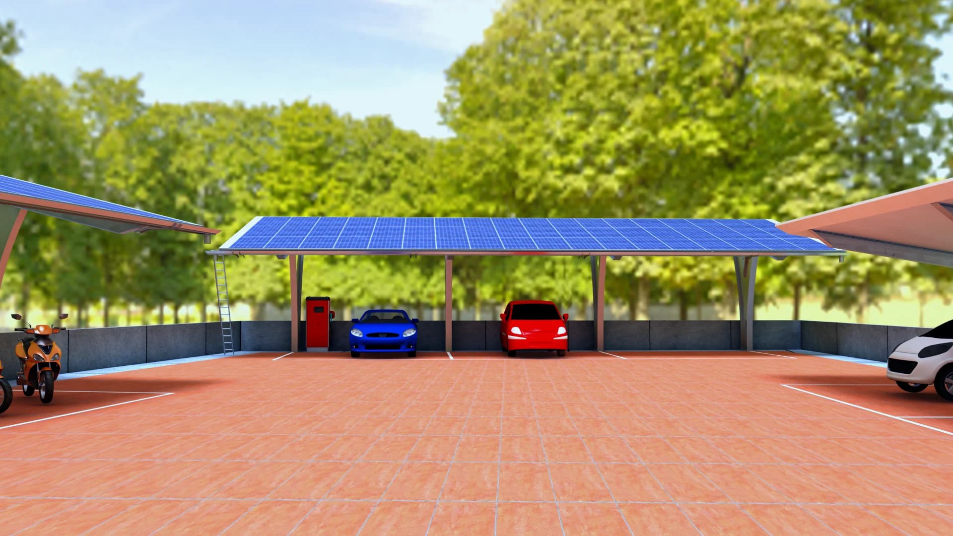
Parking and charging interface
The eye-level view communicates the space beneath the canopy and the relationship between vehicles, supports and charging points
11 / Development Outputs
An engineering package for continued development
| WORKSTREAM | DOCUMENTED PROJECT OUTPUT |
|---|---|
| Concept development | Alternative canopy and support assemblies |
| Detailed design | Dimensioned concept drawings and connection studies |
| Assembly planning | Step-by-step CAD sequences with local fit-up views |
| Structural investigation | Support deformation and critical-connector stress views |
| Product communication | Parking-site renders and integration views |
These are design requirements. The following concepts explore different ways to address them
A coordinated basis for carport development
The project brought the canopy form, assembly strategy and connection detail into a coordinated design package. Concept models made the architecture visible, assembly sequences explained how the parts came together, and structural plots exposed the behaviour of the central support and its critical joint. The site visualisations then placed the product within a parking and energy infrastructure layout, supporting discussion of how the carport could be applied.