Smart wall
Motion and control for adaptable living spaces
Product Design & Development
Smart Wall
- Requirement
Make the room adapt to its use
Coordinate wall movement with the bed, table and desk so the system can change configuration through simple physical controls.
- Challenge
Coordinate motion, sensing and access
Bring drives, brakes, locks, position inputs and obstacle checks together in a control package that can be assembled, inspected and tested
- Deliverables
An integrated prototype package
Control architecture, custom electronics, panel assembly, handheld and wired controls, prepared harnesses and prototype motion demonstrations.
- Station and direction commands
- Wall movement
- Table, desk and bed interfaces
- Furniture functions
- Sensing, drives and user inputs
- Integrated controls
The Development Process
An integrated approach to a moving product
Step 01: Define
Map user actions, movement states and input checks
Step 02: Develop
Allocate control signals and build the custom electronics.
Step 03: Integrate
Bring the panel, drives, sensors and frame together.

Step 04: Evaluate
Work through calibration and movement demonstrations.

Step 05: Package
Enclose the hardware and organise the cable and sensor kit.
01 / Product Architecture
A physical wall prototype for motion development
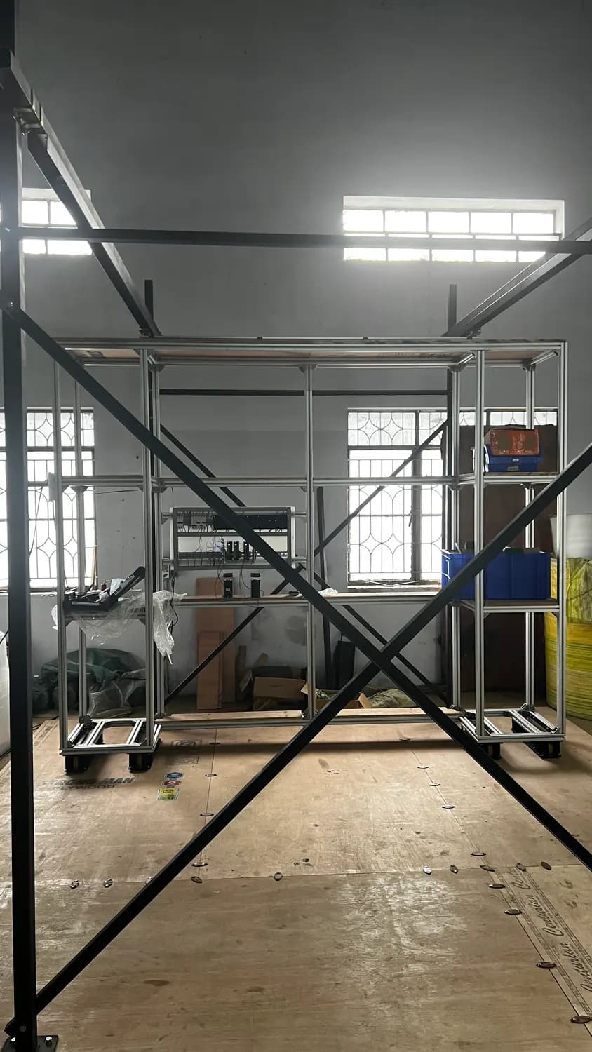
The full-height development assembly
The aluminium-profile frame provided a physical platform for wall-motion development. The surrounding black steel rig supported the workshop demonstration setup.
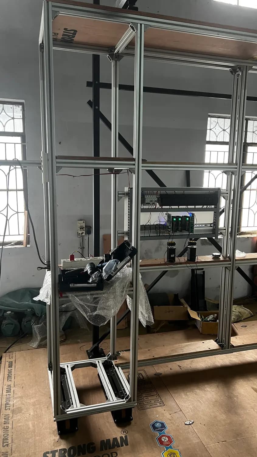
The mechanical interfaces
Internal bays, lower wheel assemblies and mounting rails brought the moving structure and control hardware into one testable assembly.
02 / System Concept
Define the control architecture before wiring
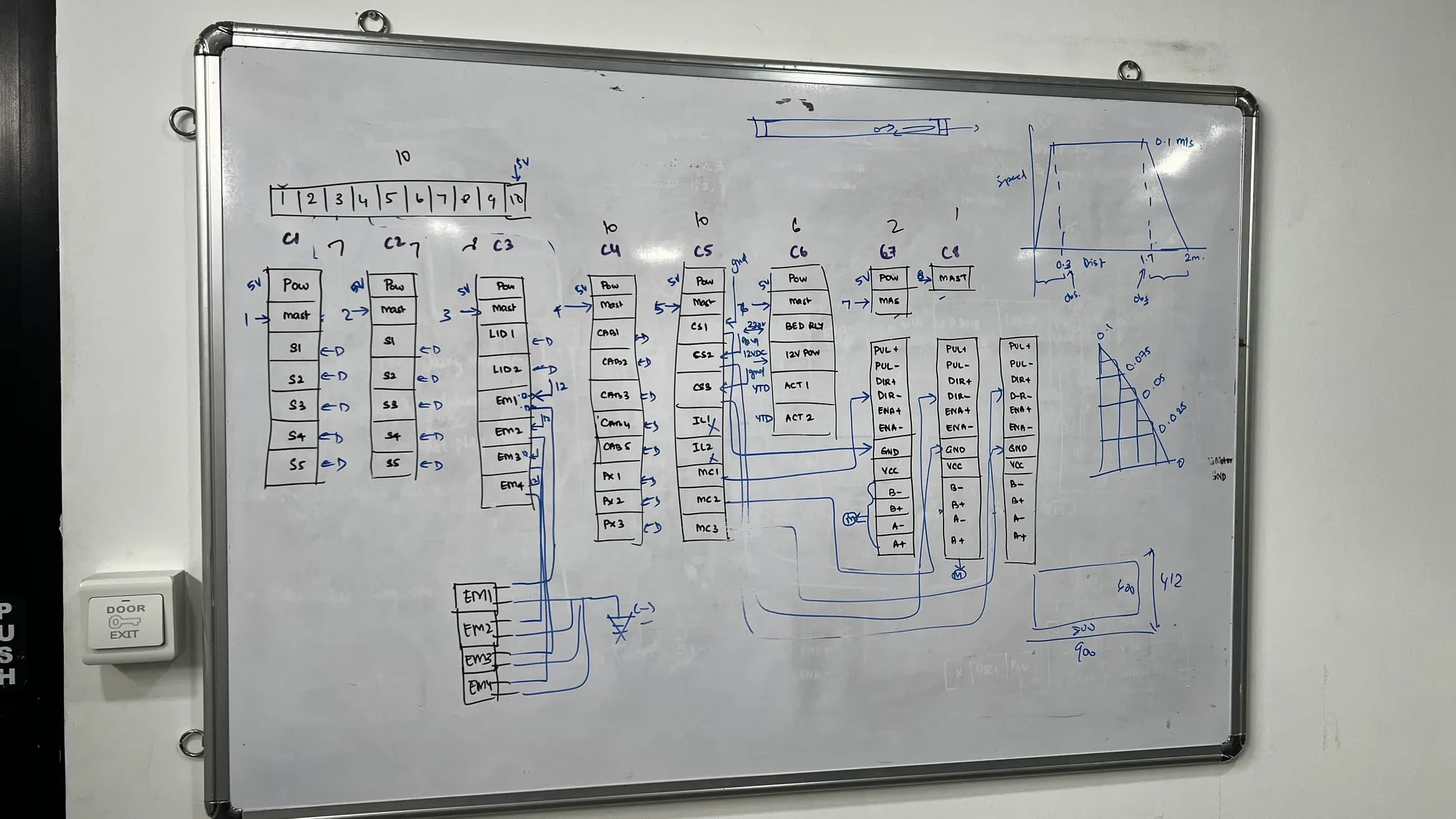
The early hand-drawn architecture mapped controllers, motor-drive signals, locks, sensors and auxiliary functions. This established how commands and feedback would move between the user interface, control electronics and physical hardware Original engineering working sketch. Handwritten values describe design planning rather than verified final specifications.
03 / Operating Sequences
Turn user commands into coordinated actions
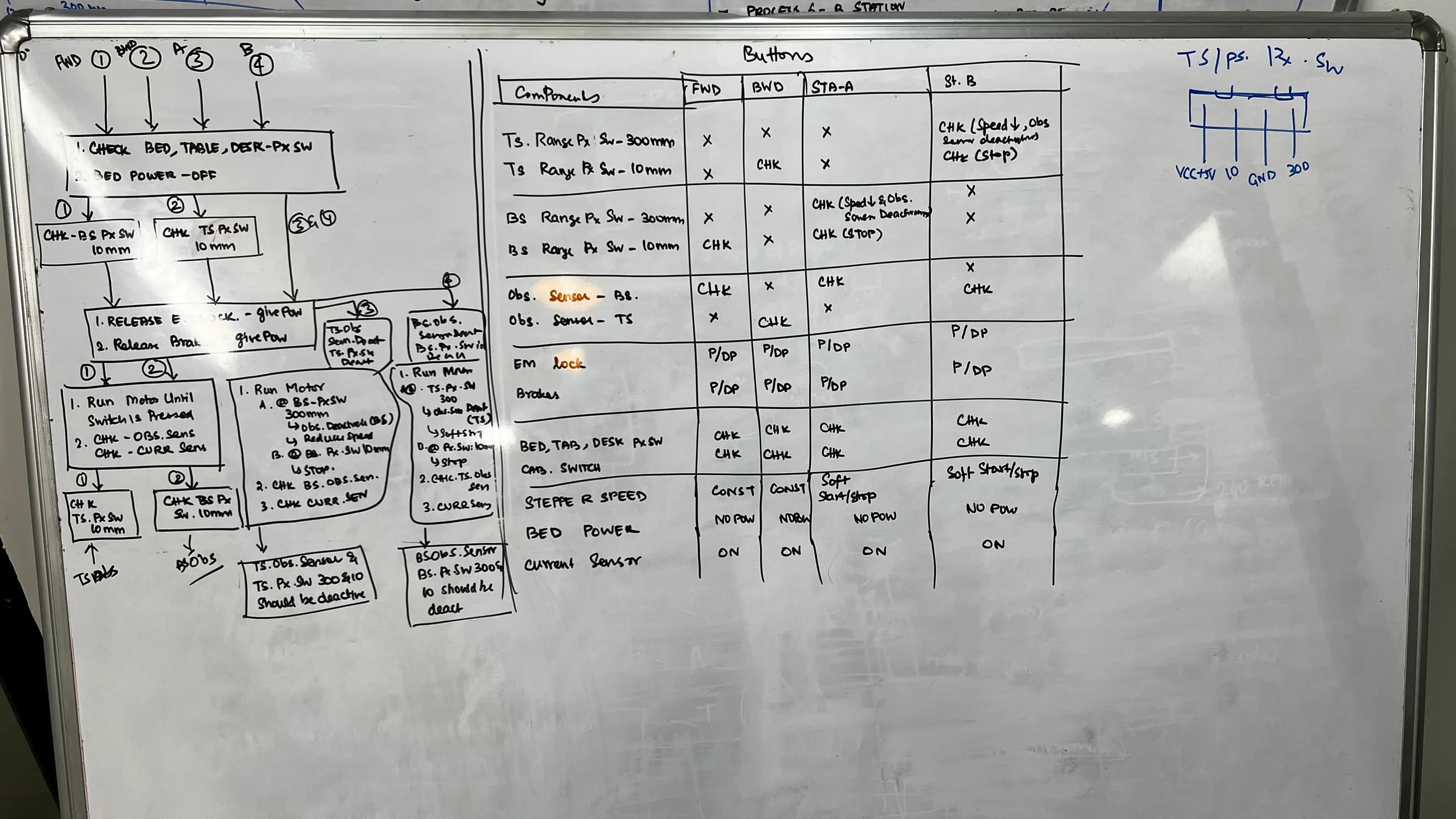
The development notes linked forward, reverse and station commands to preconditions, motion and stopping checks. The wall had to respond to the state of the furniture as well as to the requested direction.
| DEVELOPMENT STEP | ROLE IN THE SEQUENCE |
|---|---|
| Check the initial state | Review bed, table and desk position inputs before motion |
| Prepare the mechanism | Coordinate the electromagnetic locks, brakes and drive enable |
| Manage travel | Use direction, position, obstacle and current inputs during movement |
| Approach the target | Reduce speed and check the final position in the station sequence |
04 / Motion Development
Plan the start, travel and approach to a stop
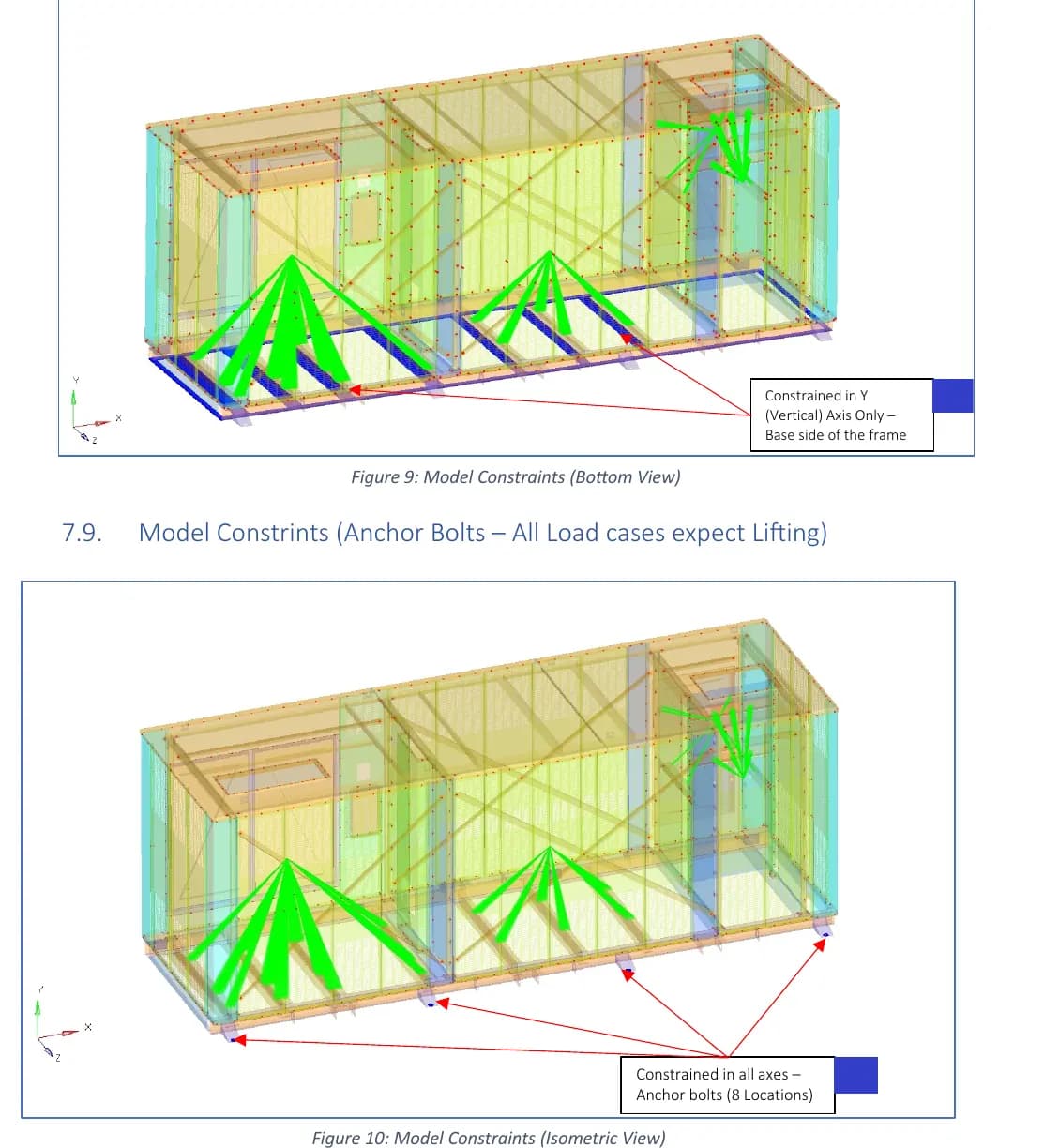
Original report: revision 02, page 17. Lifting uses the separate arrangement shown later
Motion quality is part of the product experience
The team sketched how the moving wall should accelerate, travel and decelerate near its destination. The operating matrix also distinguished direct movement commands from station moves with a soft start and stop.
Start
Establish the required input state and release sequence.
Travel
Coordinate the drive channels while monitoring the relevant inputs
Approach
Use position information to transition toward the final stopping point.
Prototype Development
The design progressed into a physical build
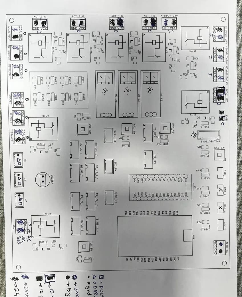
Board layout
The photographed layout artwork connects the circuit concept to component placement and board routing.
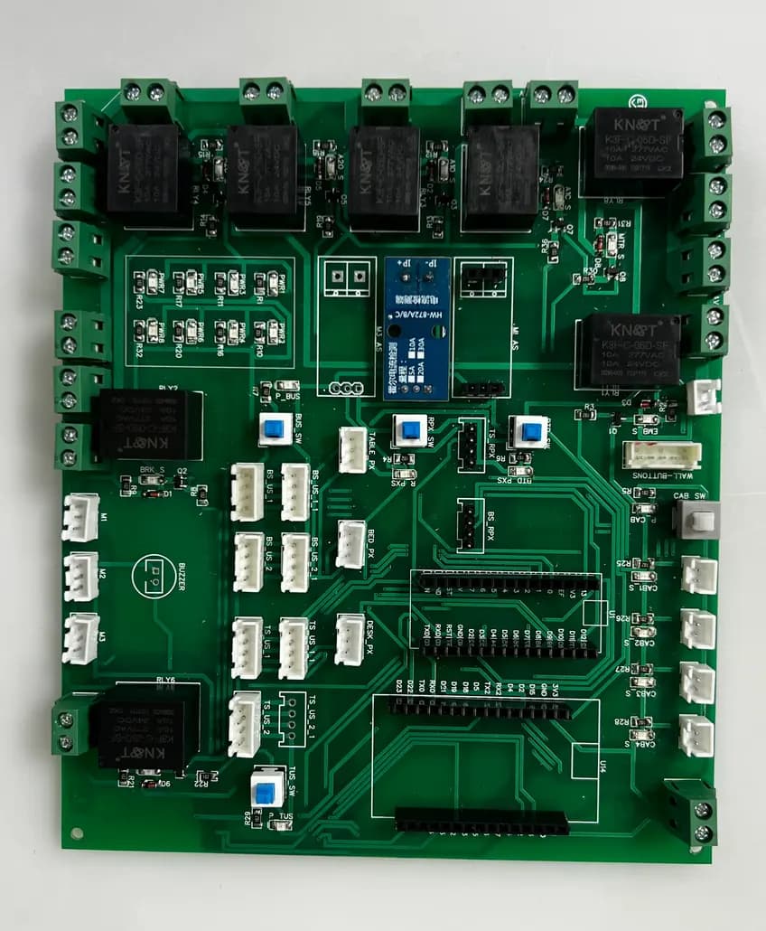
Populated PCB
Relays, connectors and interface circuitry were assembled around the control and sensor connections.
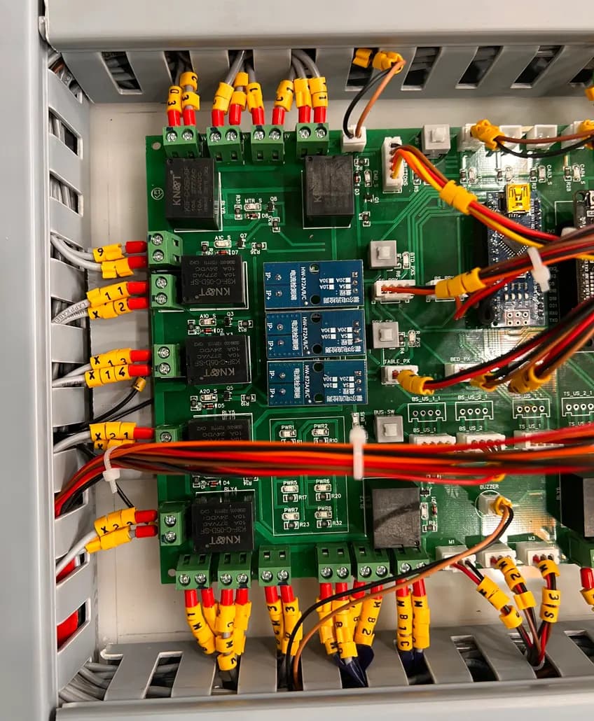
Integrated electronics
The board was fitted with controller modules and connected to the labelled field wiring.
06 / Prototype Integration
Bring the panel and the mechanics together
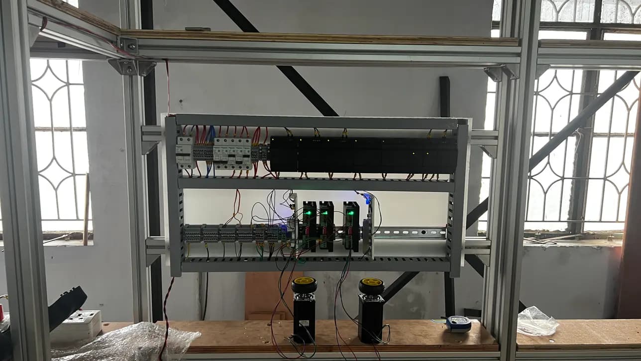
On the wall frame
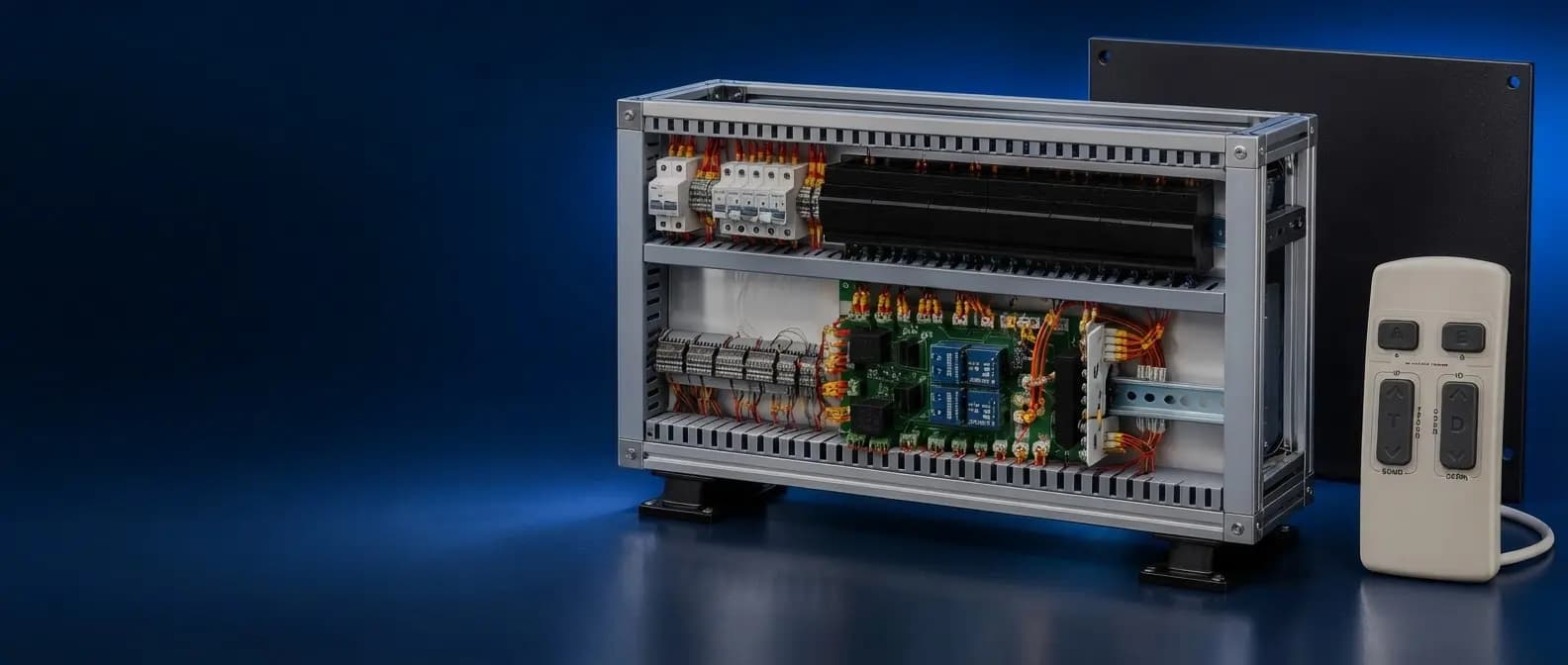
The early panel placed the controller hardware, protection and drive channels directly on the full-size assembly. This made the electrical-to-mechanical interfaces visible during development.
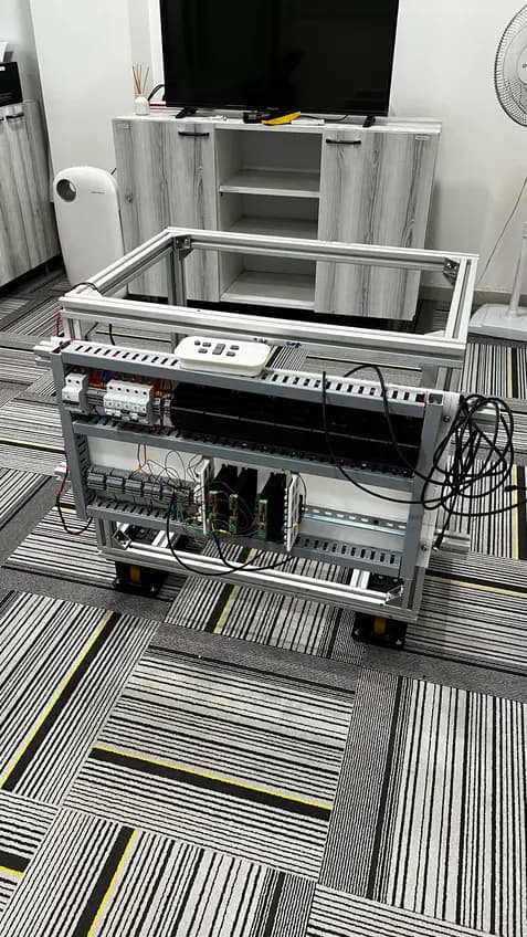
On a compact test frame
A smaller aluminium rig supported bench work on the controller, motor interfaces and user commands.
07 / Drive and Power Integration
Organise power, protection and motor connections
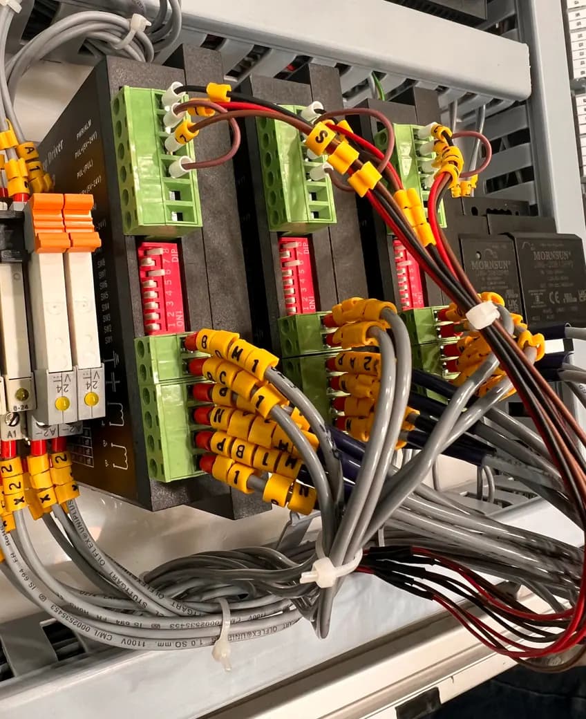
Motor-drive channels
Three driver units and their motor and signal terminals are visible in the assembled hardware.
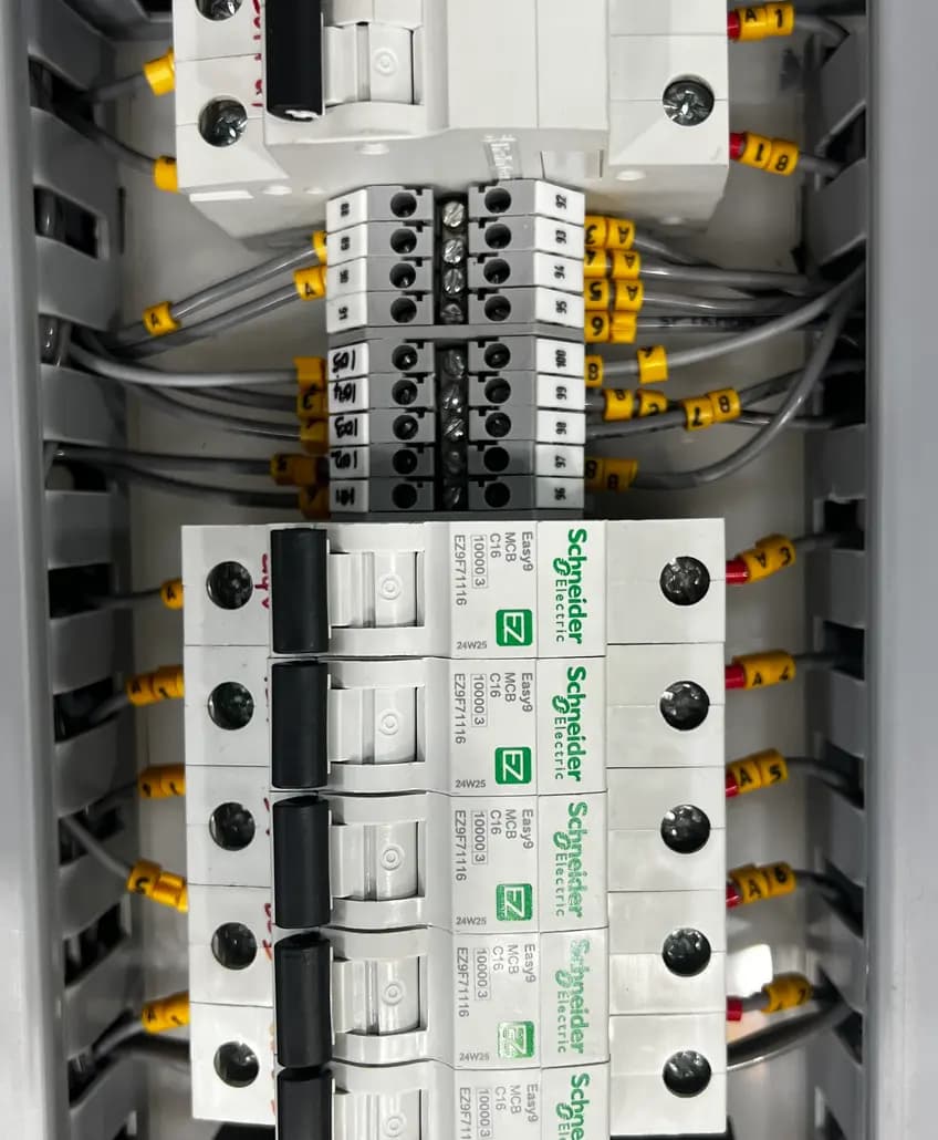
Circuit protection
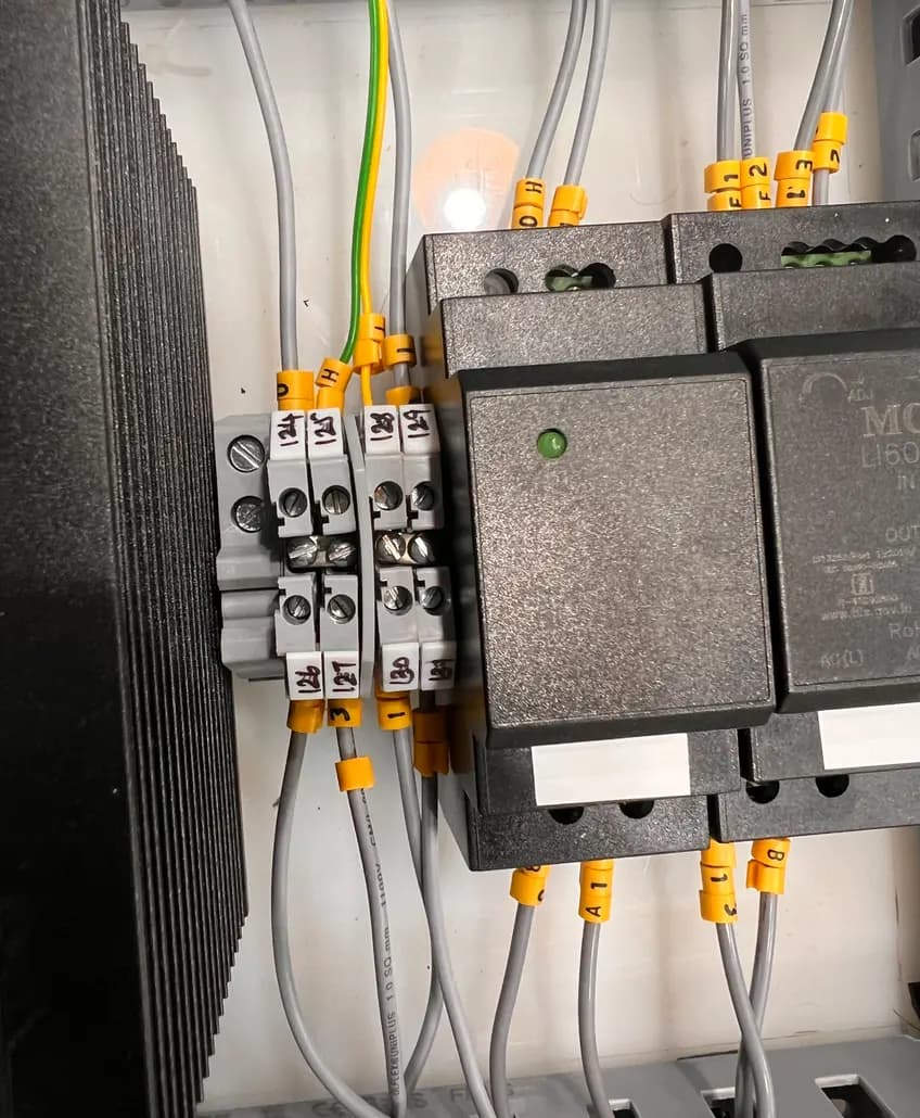
DIN-rail protection devices and cable ducts organise the panel’s power connections.
Powerdistribution
Power modules and terminal connections sit alongside the control and field wiring.
08 / Sensing and Interlocks
Link movement to what the system can detect
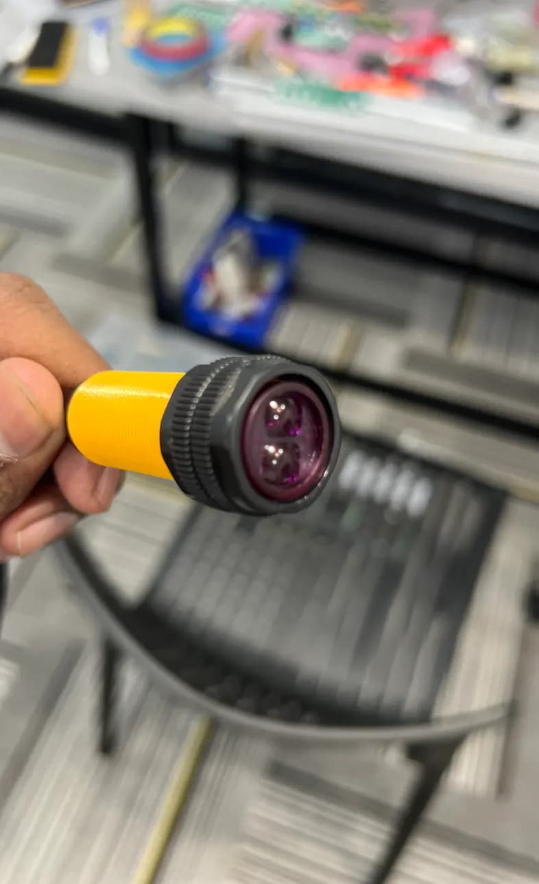
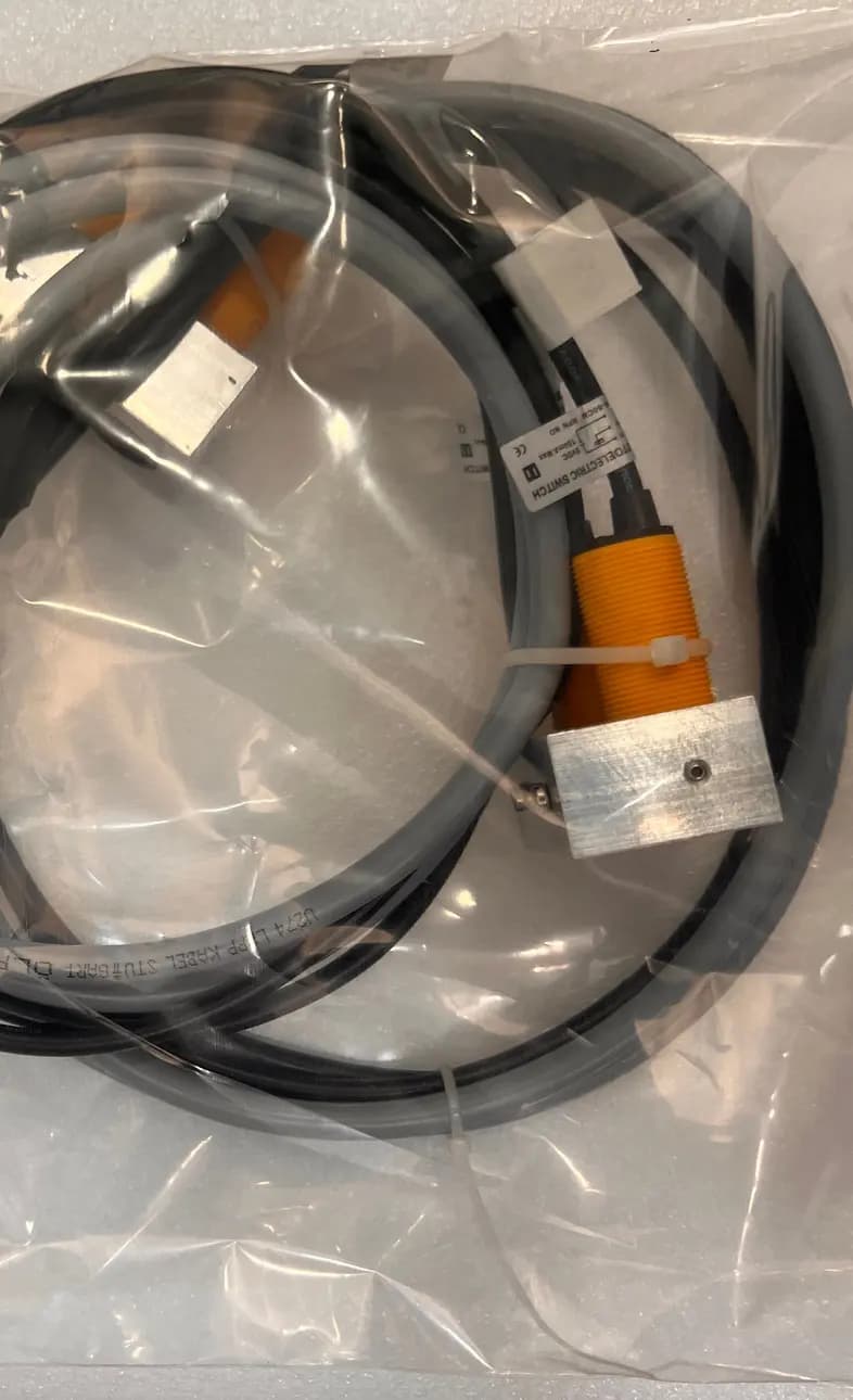
Inputs for position and condition
The calibration record includes position/ranging, obstacle, current and cabinet inputs. These were considered alongside motor, brake and lock functions as part of the movement-control logic.
The photographs show component evaluation and preparation of a sensor harness for integration.
The source record shows development checks; detection range, stopping performance and certified safety ratings are not specified.
09 / User Interface Development
Give the user direct, physical control
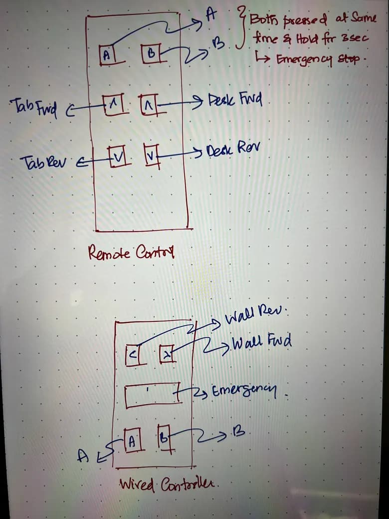
Original control concepts
Hand sketches allocated station, direction and furniture commands across the remote and wired controller
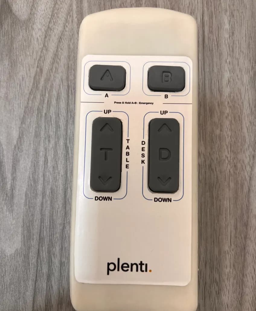
Handheld remote
The Plenti remote carries A/B station buttons and separate up/down controls for the table and desk.
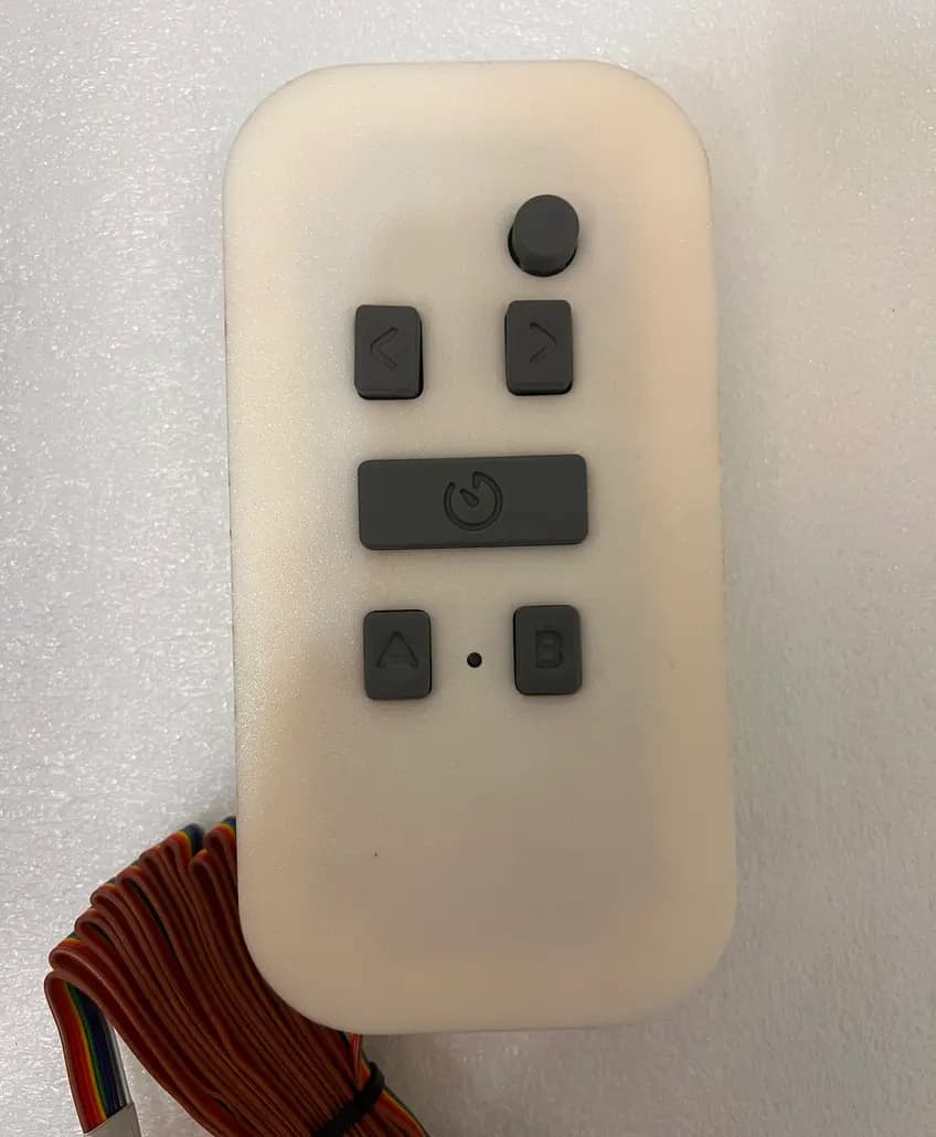
Wired control unit
The wired prototype provides a second physical interface, with direction, station and stop-related functions in the design notes.
10 / Wiring and Assembly
Make the connections identifiable and serviceable
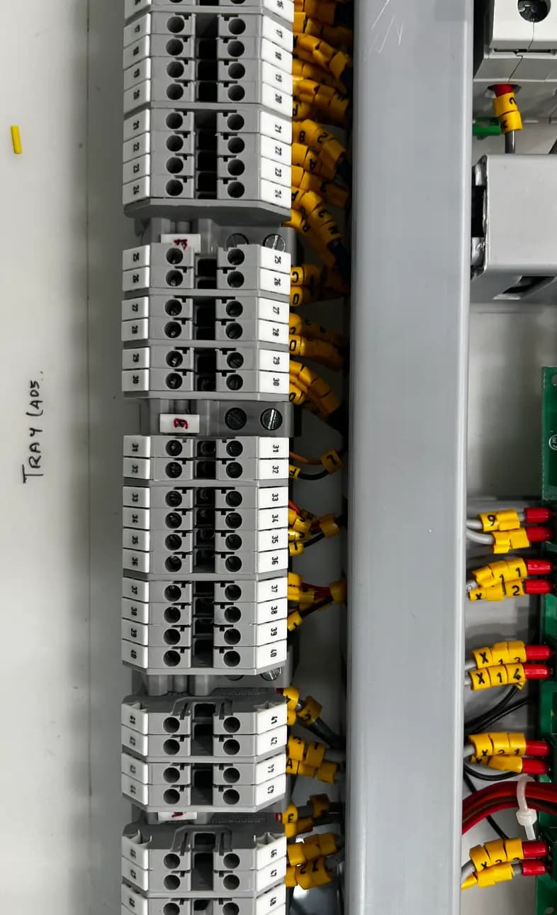
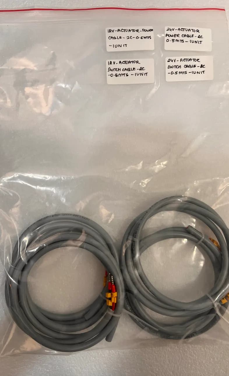
A repeatable wiring arrangement
Numbered wire markers, grouped terminals and cable ducts make individual connections easier to trace. Prepared cable assemblies support connection of the sensors, drives and controls to the main panel.
This work connects board-level design with the practical needs of assembly and fault finding
04 / Motion Development
Plan the start, travel and approach to a stop
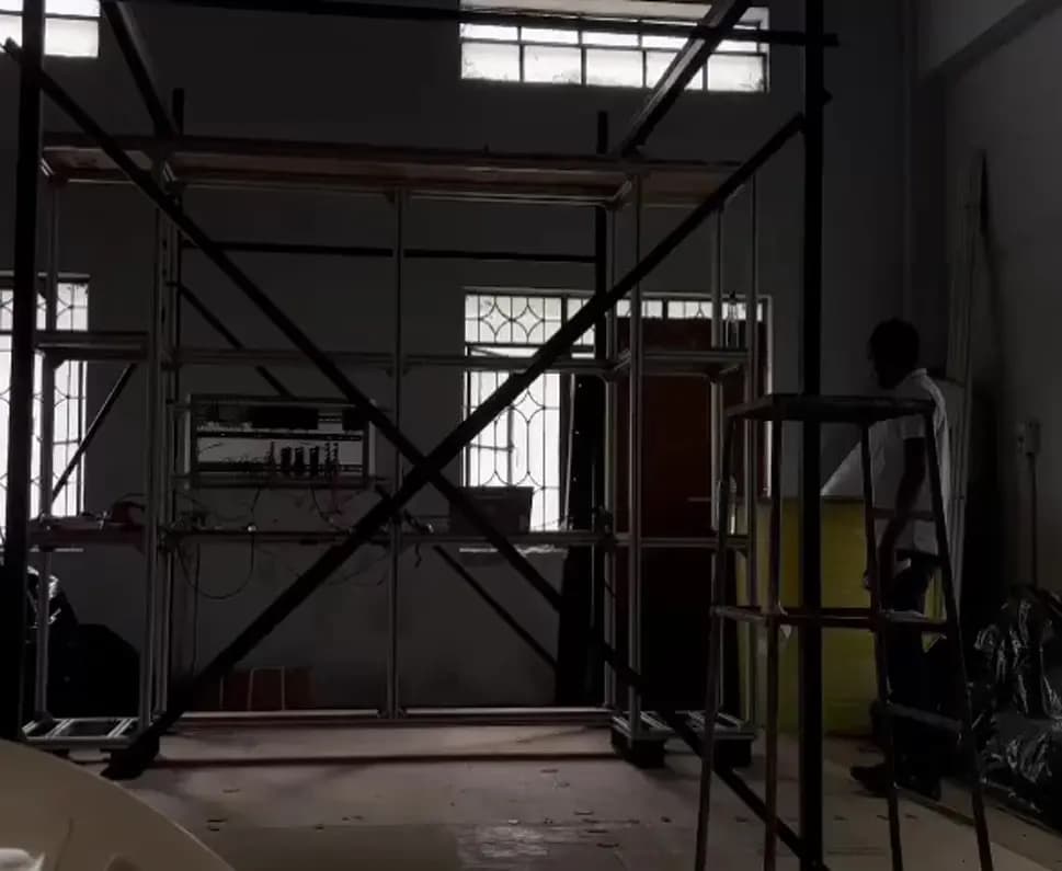
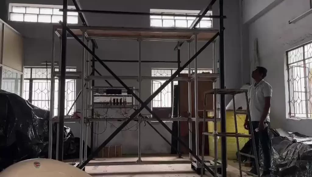
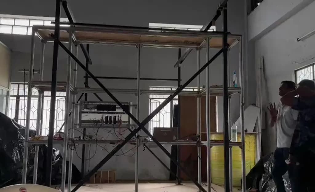
Original video frames: an early position at left, followed by intermediate and later positions at right. The workshop recording shows the wall frame changing position inside the test rig while the team observes its movement. This provides a physical demonstration of the integrated prototype. The two original motion clips are included with the project assets.
12 / Development Checks
Work through calibration and operating milestones
Component-level checks
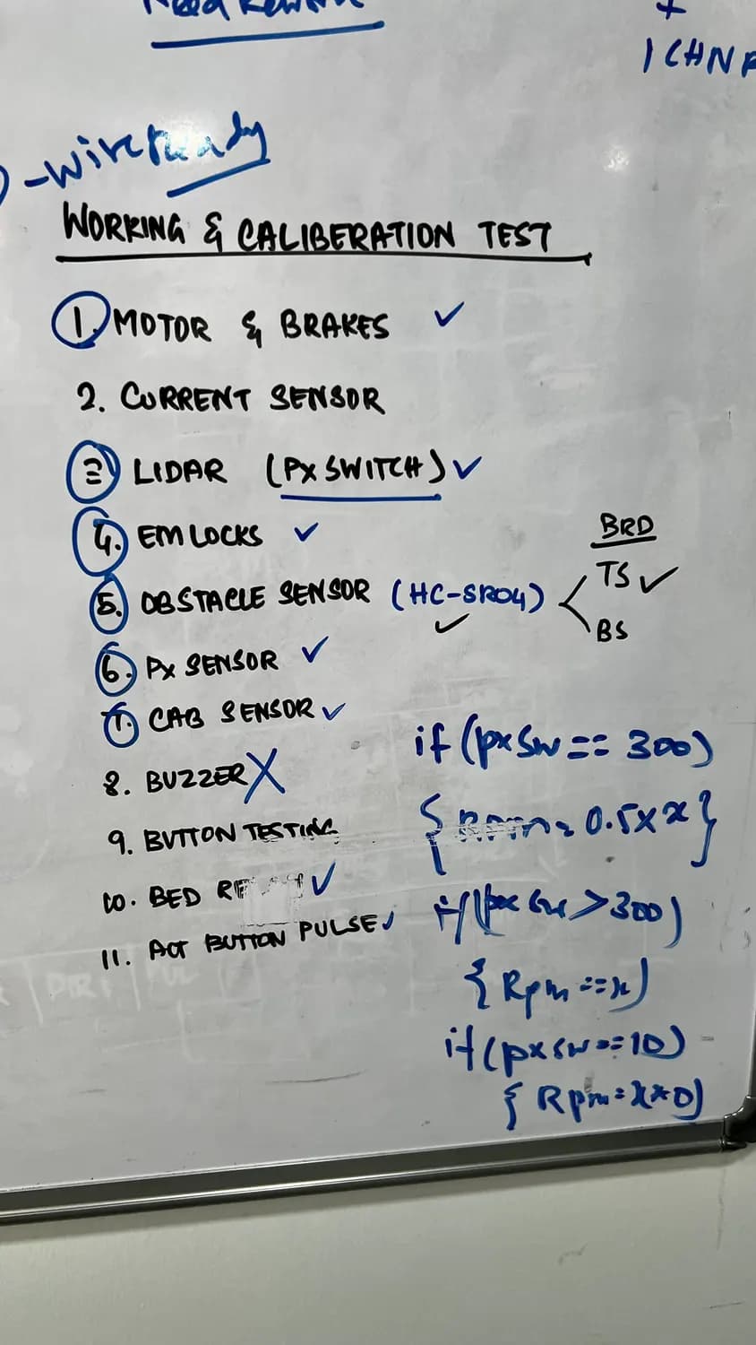
The checklist covers motors and brakes, current sensing, ranging, electromagnetic locks, obstacle and position inputs, buttons and auxiliary functions
System-level sequences
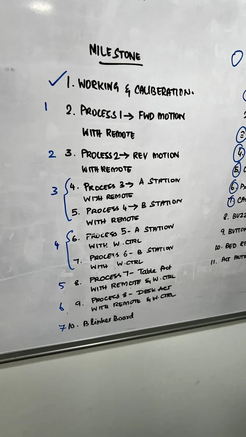
The milestone plan progresses through forward/reverse motion, station A/B commands, wired controls, table and desk actuation, and indication functions
These are original working records with mixed completion marks and open items. They document the development process, not a completed acceptance certificate
13 / Enclosure and Final Assembly
Package the electronics as a complete control unit
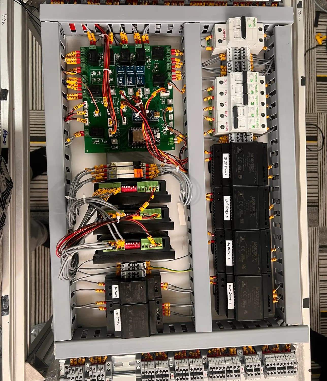
Inside the control package
The assembled panel brings together the PCB, motor drivers, power and protection devices, field terminals and cable routing
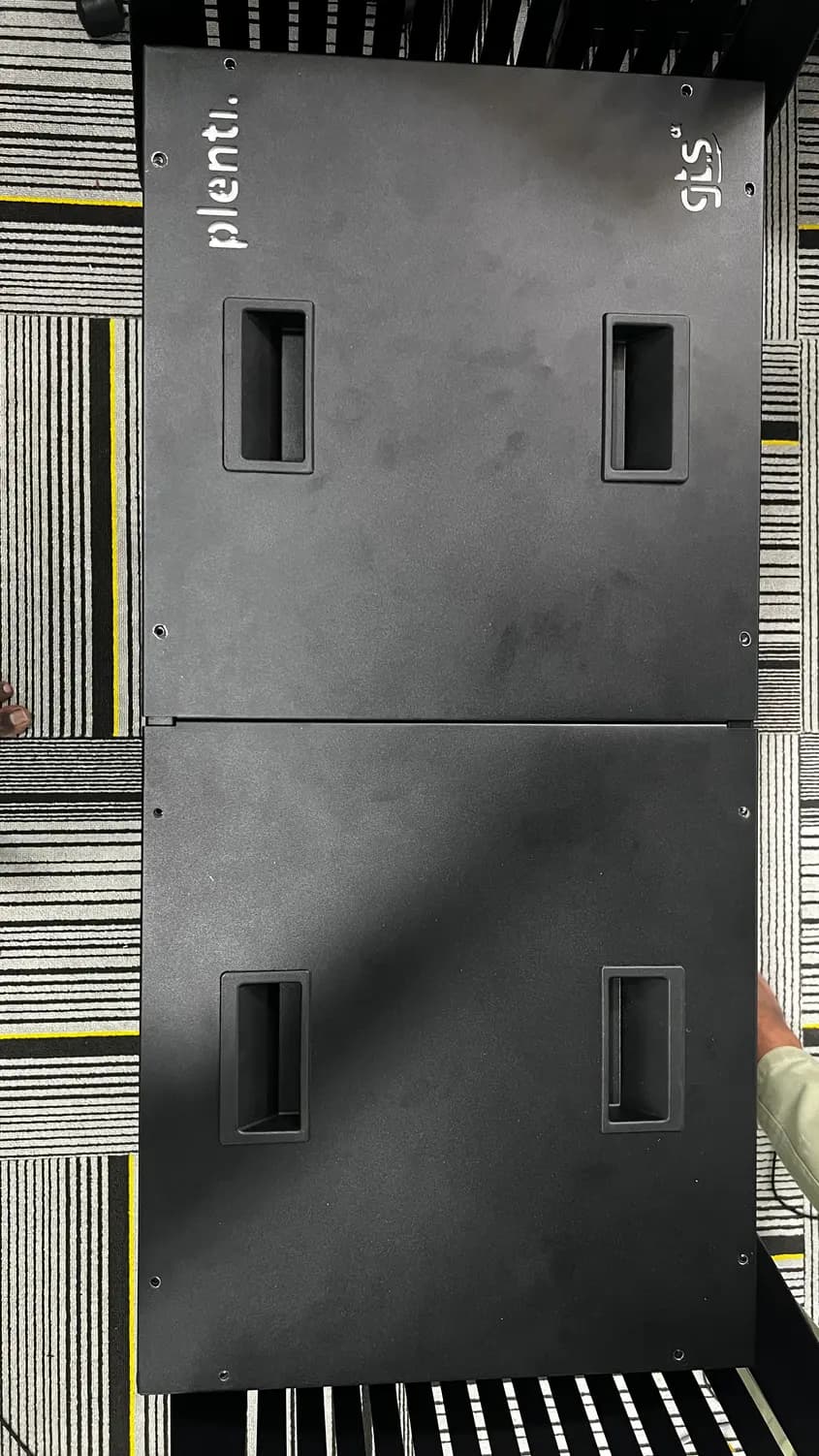
Outside the control package
Black access covers with recessed handles and project branding enclose the hardware and provide a finished service interface
14 / Component Sourcing
Carry the design into hardware procurement
Hardware sourcing connected the mechanical development to a selected standard wheel assembly. The project purchase order identifies the supplier, component reference, wheel diameter and order quantity.
| RECORDED COMPONENT | ITEM REFERENCE | PURCHASE DETAIL |
|---|---|---|
| Elesa+Ganter wheel | RE.F5-100-RSL / EG029931 | 100 mm diameter; 6 units ordered |
Based on the component maxima in Table 8, revision 02, page 86. Reference yield strength: 36.3 ksi
15 / Hardware Preparation
Prepare the enclosure and accessories for transfer
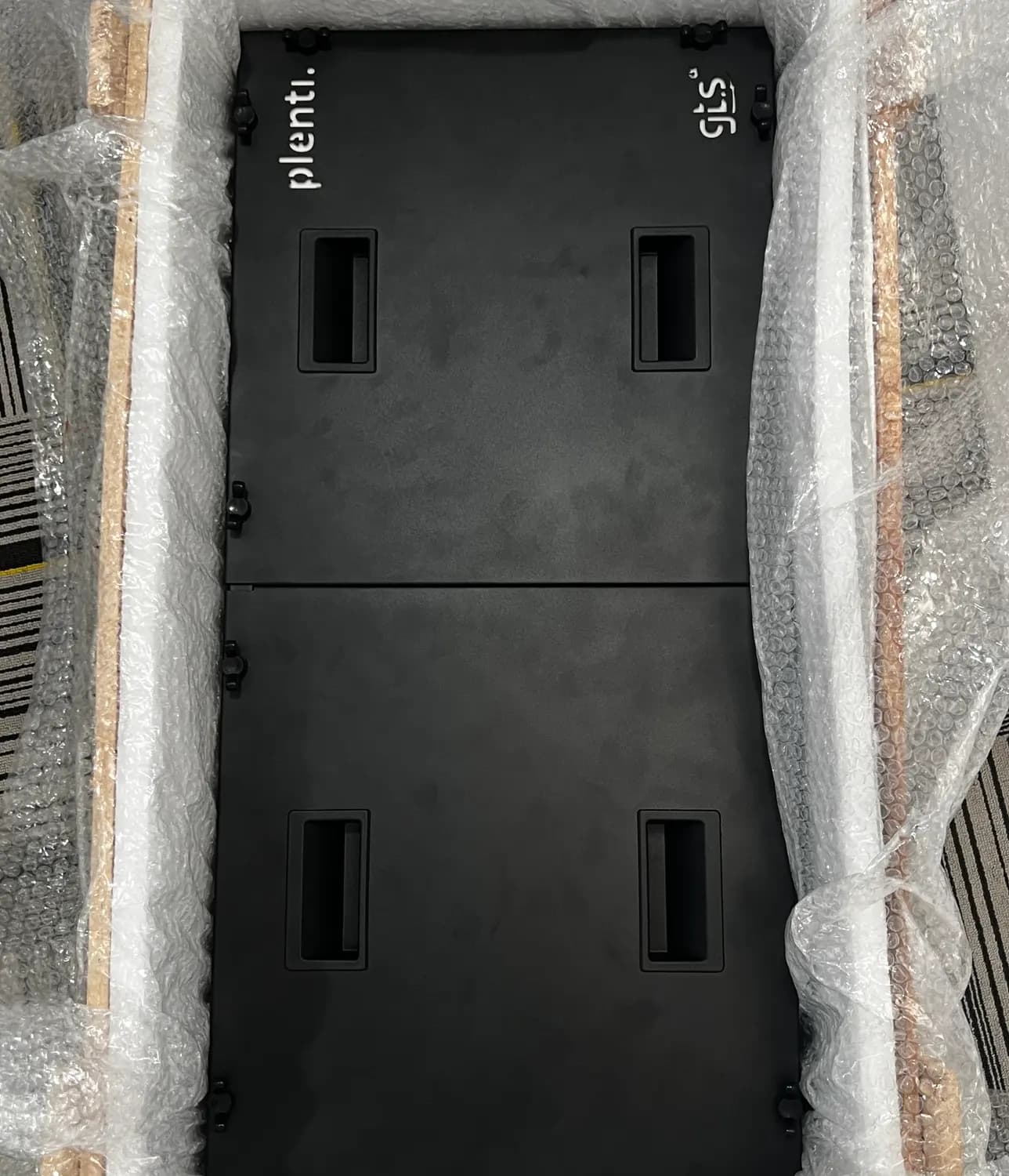
Protected main hardware
The project photographs show the enclosed control hardware wrapped and supported inside a crate
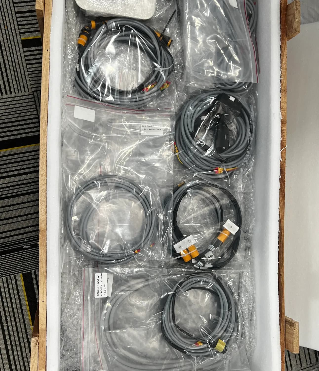
Organised accessory kit
Controls, sensor assemblies and cables were grouped separately so they could accompany the main hardware
Project Outcome
An integrated smart-wall prototype and control package
Physical development
Full-size and compact test assemblies connected the control work to the moving mechanism
Control hardware
Custom electronics, motor interfaces, physical controls and prepared harnesses formed an integrated package
Demonstration and preparation
Motion footage, working checklists and packing photographs document the prototype’s development and preparation
A coordinated system behind an adaptable room
The work brought motion control, sensing, user inputs and physical hardware into a working development platform. The record follows that platform through integration, demonstration, enclosure and packing