RoboBar
Robotic Liquor Dispensing
Product Design & Development
Robobar
- Requirement
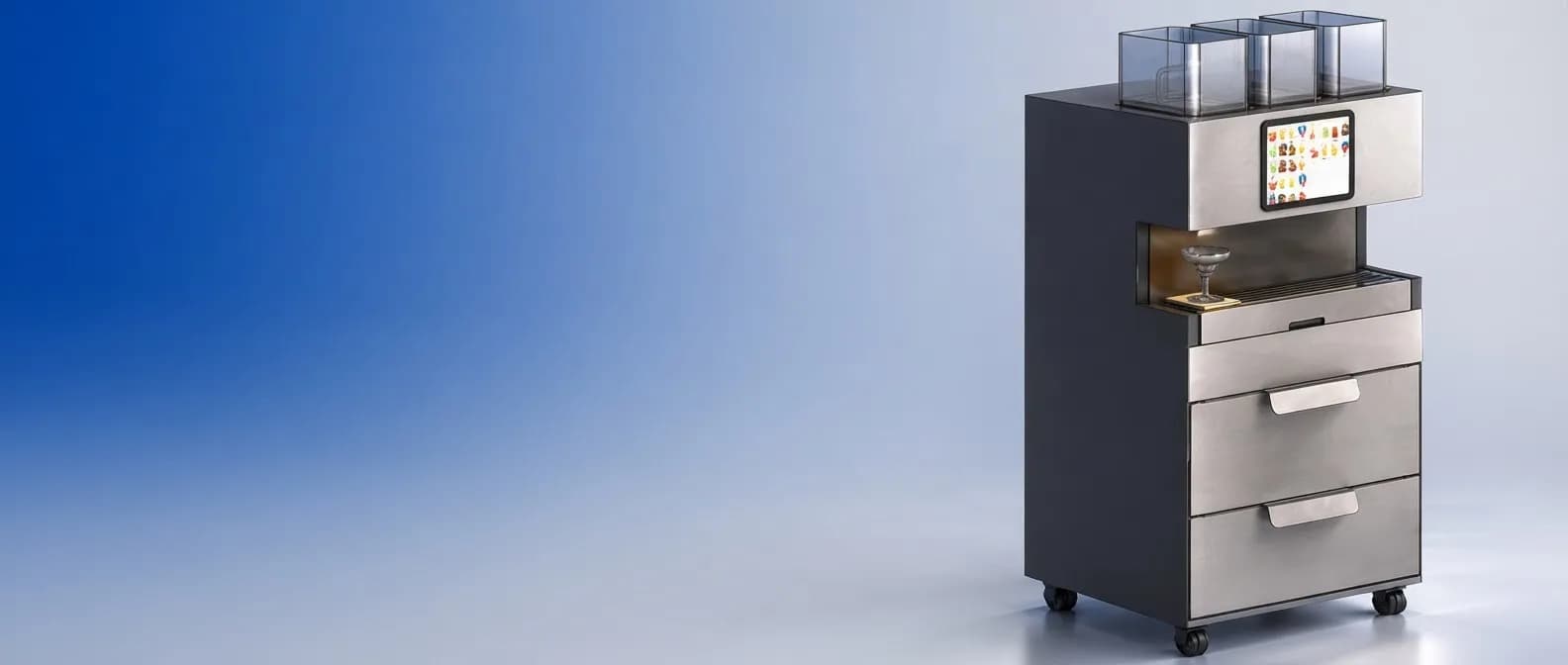
A complete drinks unit
Develop a compact product that combines liquor and juice dispensing with mint, lemon and ice handling. Provide a touchscreen interface and a mechanism to position the glass
- Challenge
Many mechanisms, one cabinet
Fit liquid storage, refrigeration and moving dispensers within the cabinet while providing access for replenishment. Coordinate each outlet with the glass-positioning system
- Deliverables
Mechanical design and software
Mechanical CAD, subsystem assemblies and two glass-handling options, together with the customer app and administrator interfaces for recipes, ingredients and machine operations
- Liquor tray capacity
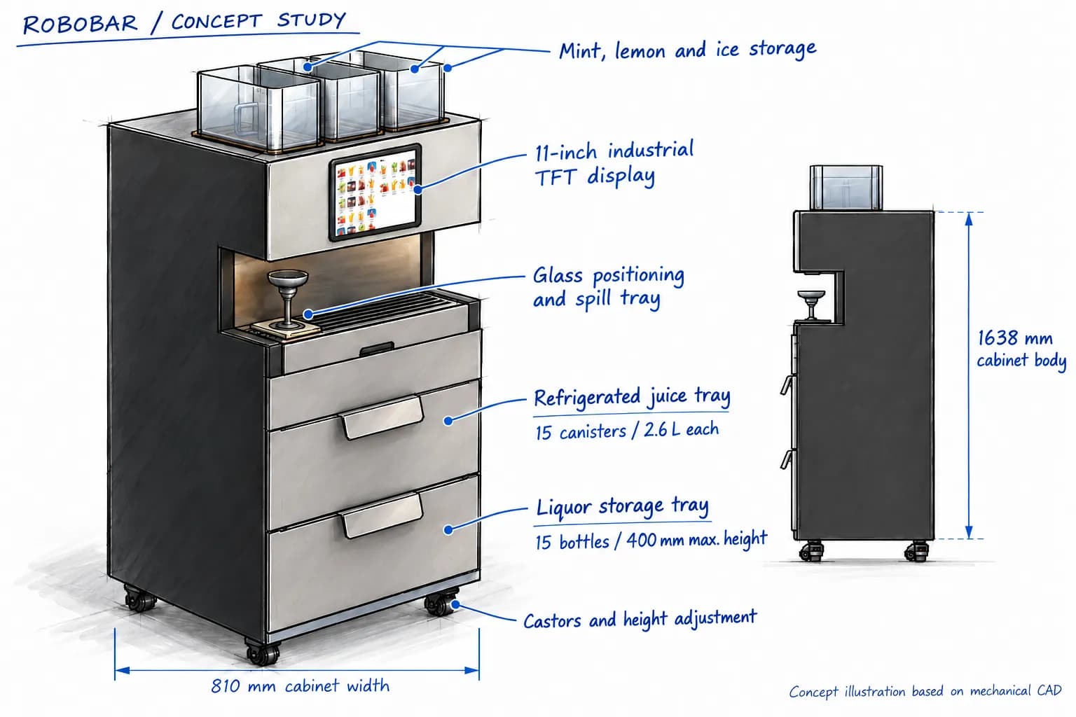
- 15 bottles
- 2.6 L per juice canister
- 15 canisters
- Lead screw or conveyor
- 2 configurations
The Product Concept
The product layout and key specifications
Concept Development
The Development Process
Mechanical design subsystem by subsystem
01 Product Architecture
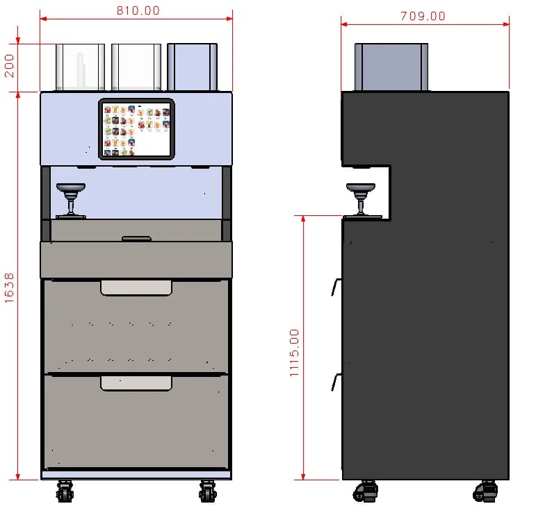
Original dimensioned CAD views
We defined the cabinet envelope and allocated space for the display, serving bay and storage drawers. Front and side views established the arrangement before subsystem detailing
02 Chassis and Packaging
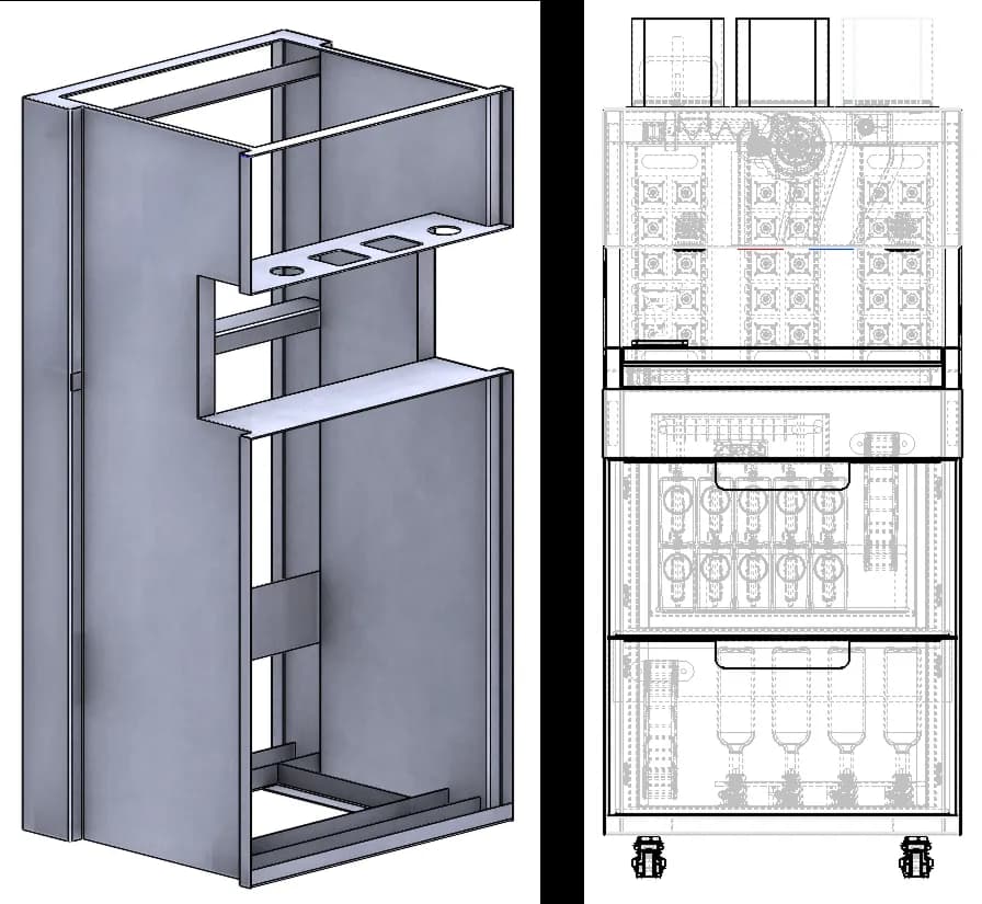
Chassis and internal arrangement. Stated chassis mass: 50 kg
A mild-steel monocoque chassis provides mounting locations for the trays, pumps and garnish mechanisms. The internal layout also accommodates the refrigeration module
03 Liquor Storage and Flow
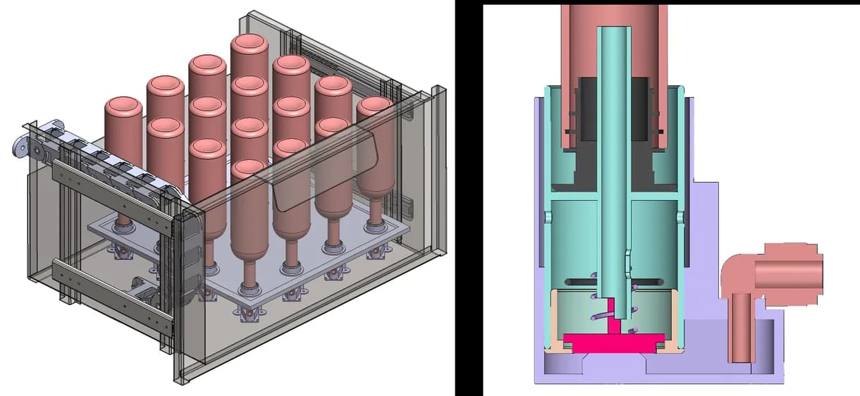
Liquor tray assembly and flow-control section
The pull-out tray holds 15 bottles up to 400 mm high. We detailed the bottle check valve and static flow-control spout, including the spring, nozzle and vent arrangement
04 Juice Storage and Refill
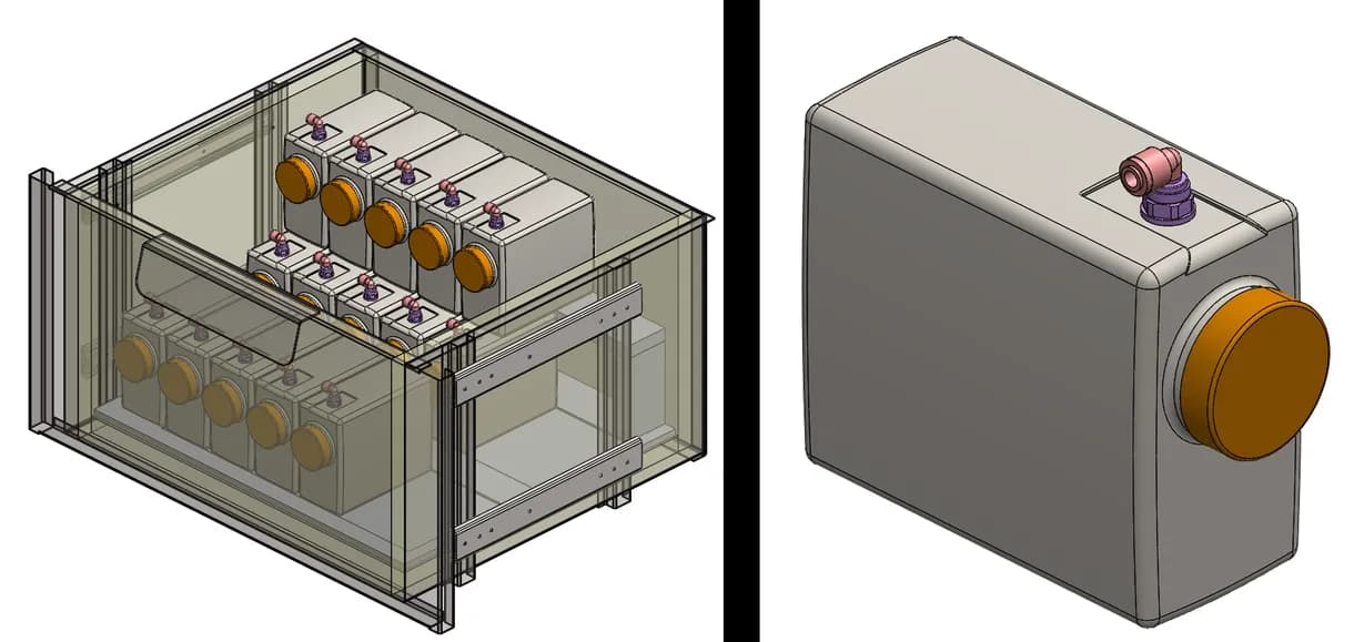
Insulated juice storage and individual canister
The insulated tray accommodates 15 juice canisters. Each 2.6 L canister has a filling cap and push-fit nozzle. Slide rails and a spill tray support replenishment and access
05 Pumps and Liquid Routing
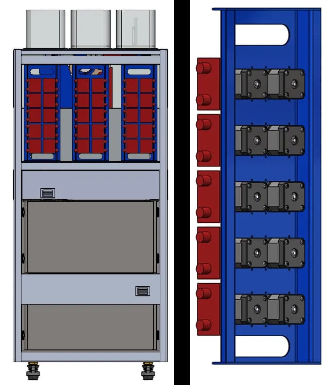
Rear integration and pump mounting detail
The design provides two banks of 15 pump positions. The mounting arrangement coordinates the liquid-delivery hardware with the cabinet, alongside tubing and fitting selections.
06 Refrigeration Packaging
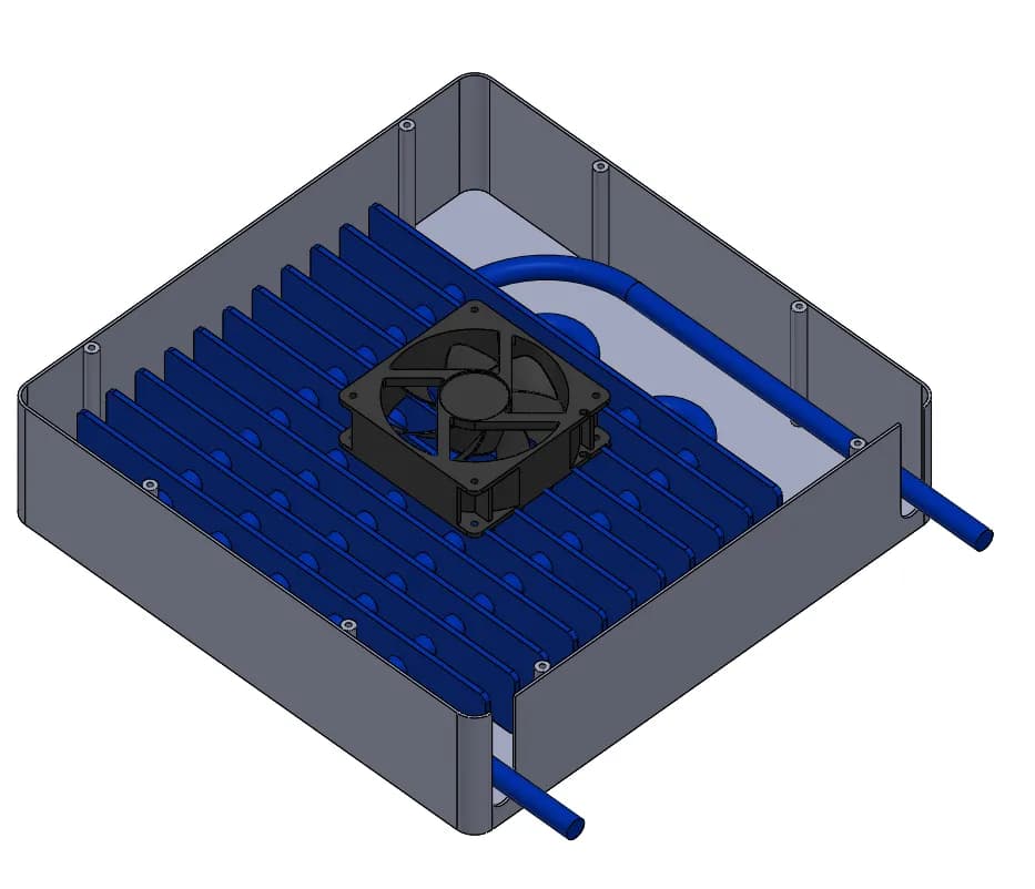
Refrigeration module with coil and axial fans
We packaged the coil and fan assembly within the refrigerated storage system. A drag chain guides the tubes as the tray moves, linking service access with the cooling layout
Ingredient Handling
Dedicated mechanisms for mint, ice and lemon
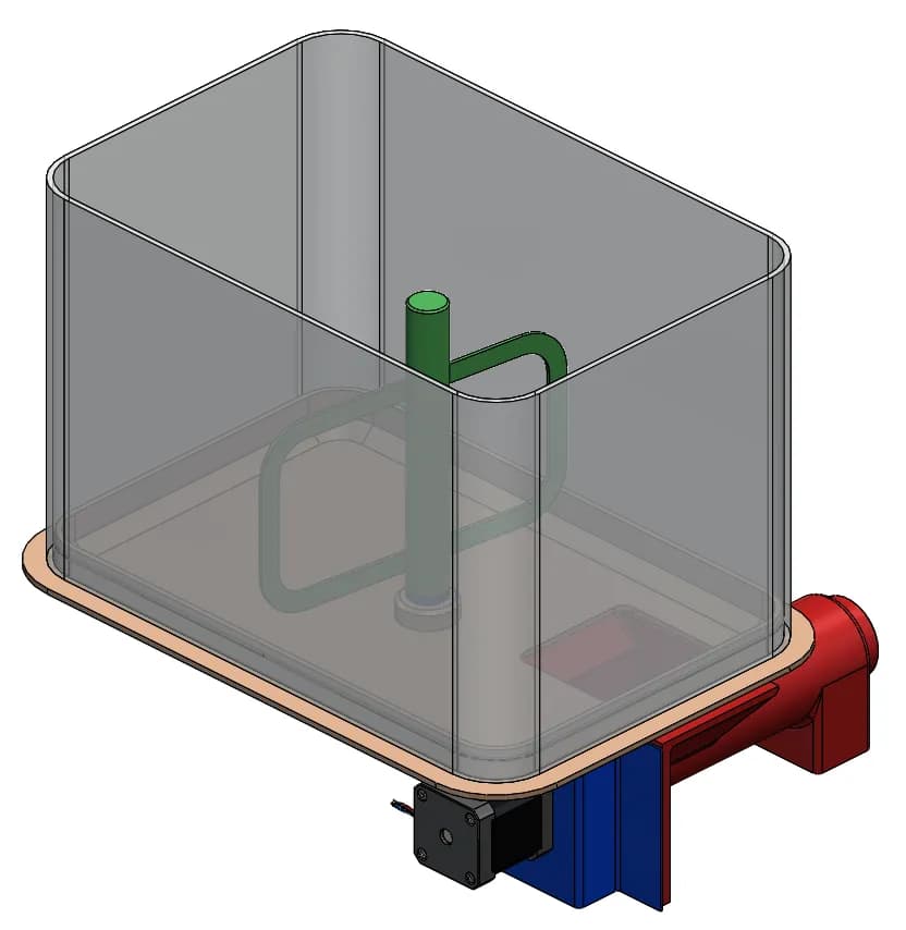
07 Mint Dispensing
A mixer and spiral conveyor form the mint-handling mechanism beneath the storage bin. The design identifies a 6 rpm synchronous drive for the mixer
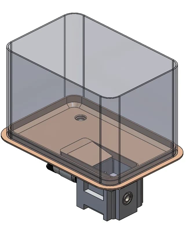
08 Ice Dispensing
The ice bin feeds a cutter and crusher driven by a DC geared motor. The layout includes a feeding vent and a separate water-drain provision
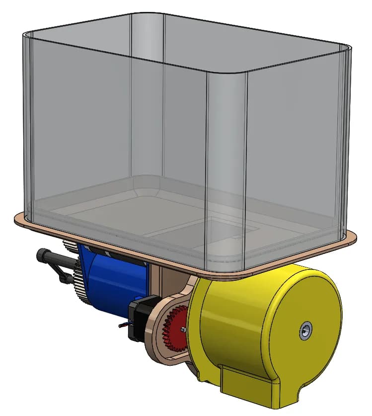
09 Mint Dispensing
A plunger, blade and rotary mechanism combine wedging with dispensing. The source design specifies lemons between 2.5 and 3 inches in diameter
Glass Positioning
Two layouts for different service formats
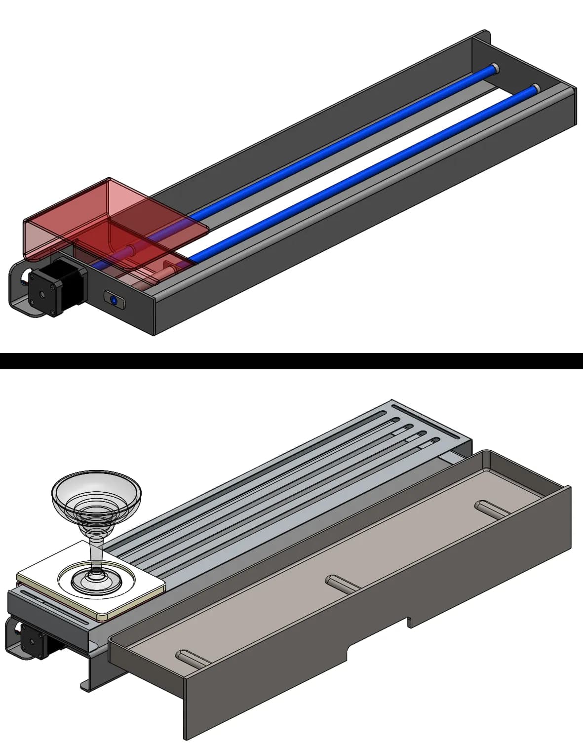
10 Standalone Configuration
Lead-screw drive and glass tray assembly
The lead-screw assembly moves the glass beneath the dispensing area. The design combines a NEMA17 motor with a guided carriage, backlit glass platform and spill tray.
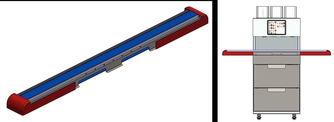
11 Conveyor Configuration
Conveyor mechanism and integrated product option
An alternative conveyor arrangement supports a queue of up to three glasses. The CAD shows how the extended glass-positioning system integrates with the same cabinet layout
App Development
The software behind the RoboBar experience
Our development scope also included the RoboBar app, with separate customer and administrator experiences. The interface connects drink selection and ordering with the recipes, ingredients and operating controls needed to manage the unit
Customer app · from machine identification to order

Identify the machine
Scan the unit’s QR code to reach its drinks menu
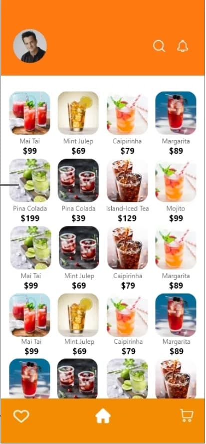
Browse the menu
Explore drinks visually, search and revisit favourites.
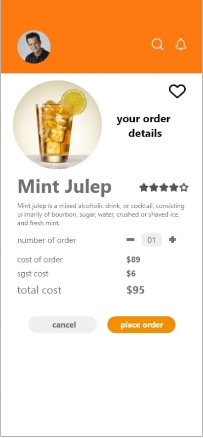
Review and order
Check the drink, quantity and displayed price before ordering
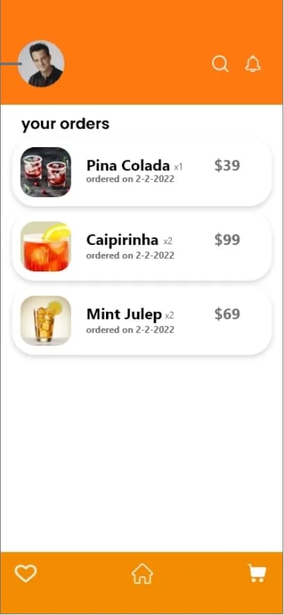
Revisit orders
View previous selections alongside the profile and menu navigation
Administrator App
Manage the RoboBar’s daily operations
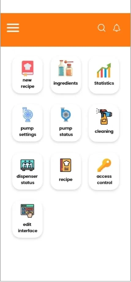
One operating dashboard
The administrator home groups recipe management, ingredients, statistics, pump controls, cleaning, access and menu editing
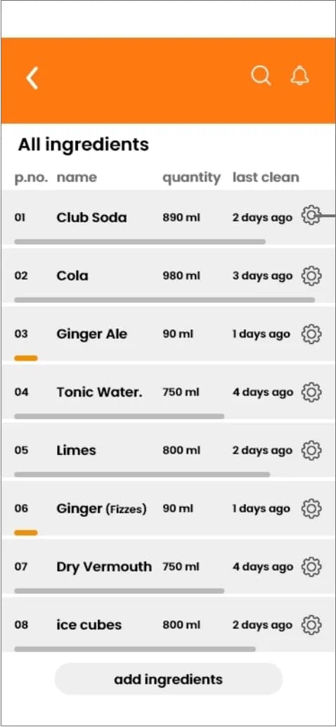
Ingredient management
The ingredient screen brings quantities and cleaning history together, with access to ingredient and pump actions
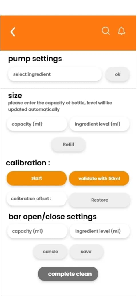
Pump setup and calibration
The pump interface provides capacity and refill fields, a calibration workflow and controls for cleaning and saved settings
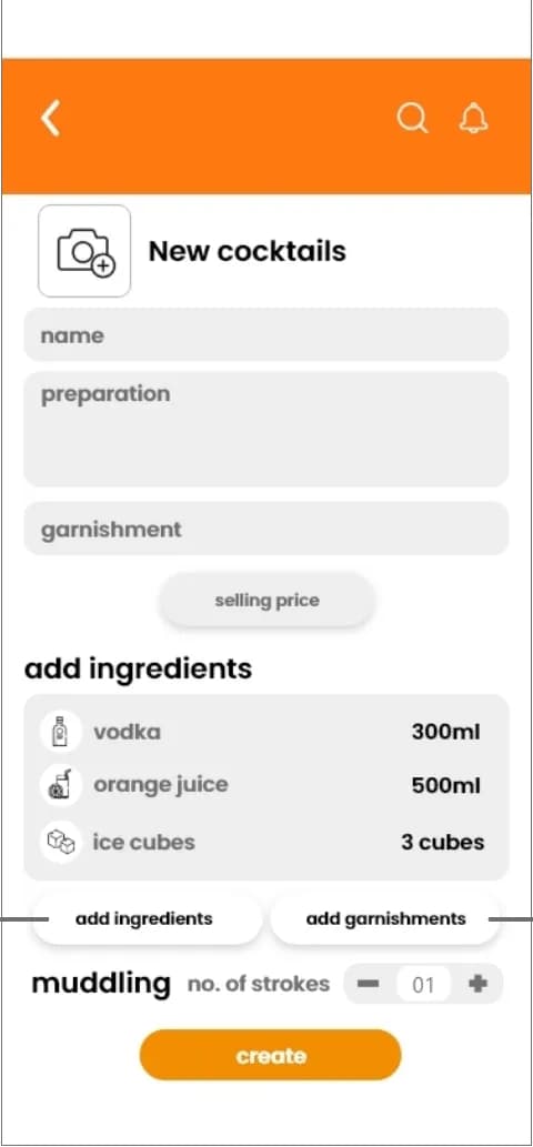
Recipe configuration
Recipe creation combines drink details, ingredient quantities, garnishes and muddling strokes in one editing flow
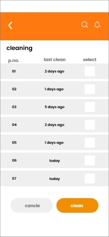
Cleaning controls
The cleaning screen identifies individual pumps, shows their last-cleaned state and provides selection controls for the cleaning operation
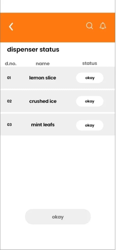
Dispenser status
The status view gives operators a separate check on the lemon, crushed-ice and mint dispensers
Original UI snapshots from the supplied RoboBar app design document. Screen prices, quantities and status values are illustrative interface content
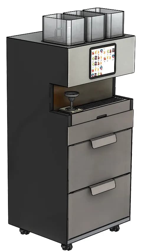
Mechanical design and app development
The product work brings the dispensing mechanisms into one cabinet and adds the app experience for customers and operators. Mechanical CAD and the customer and administrator interfaces together document the product development scope. Development scope: mechanical design, customer app and administrator controls