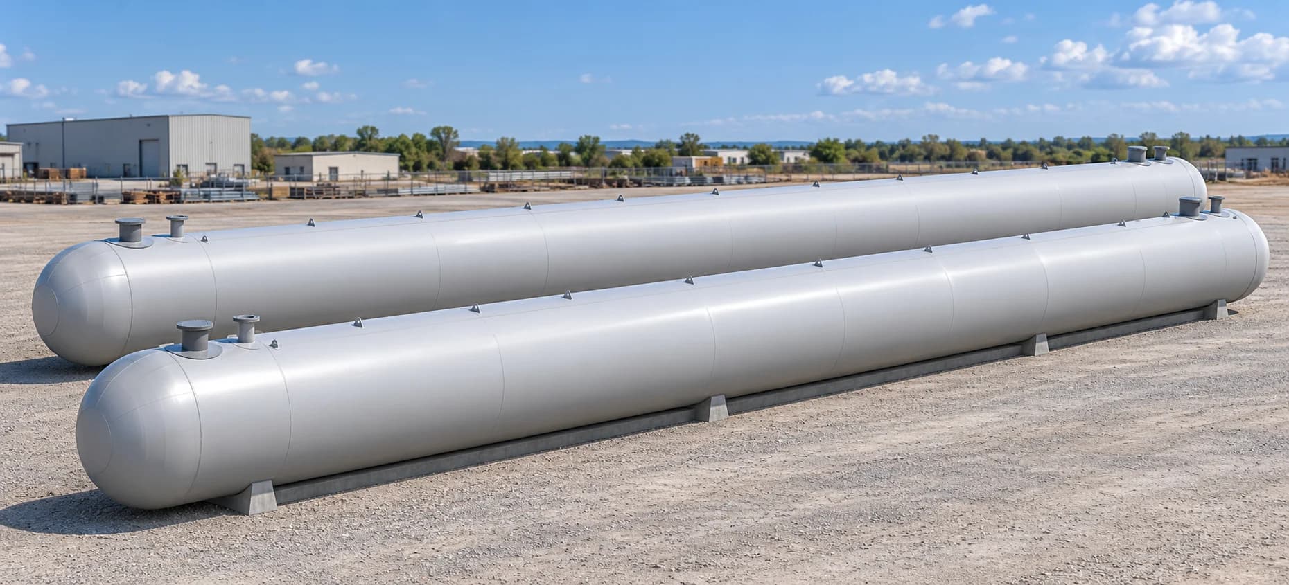
Structural FEA of LPG Bullet Tanks
ASME Section VIII, Division 2 Design by Analysis with SCL evaluation
FINITE ELEMENT ANALYSIS
Structural FEA of LPG Bullet Tanks
- Requirement
ASME VIII-2 assessment
Assess propane and butane vessels using the ASME Section VIII, Division 2 Design by Analysis basis across the defined loading conditions
- Challenge
Resolve global and local response
The long shell, openings, reinforcement pads and internal rings carry different stresses. Support assumptions and load direction also change the response
- Deliverables
An engineering assessment package
FE models, load definitions, component contours, Stress Classification Line (SCL) evaluations and documented geometry changes for engineering review
01 / VESSEL ARCHITECTURE
Understanding the complete tank assembly
Both models combine a long cylindrical shell with dish ends, internal ring stiffeners and top-mounted connections. The analysis follows how loads travel through this assembly and concentrates on the transitions around openings, reinforcement pads and attachments
01 Propane Vessel
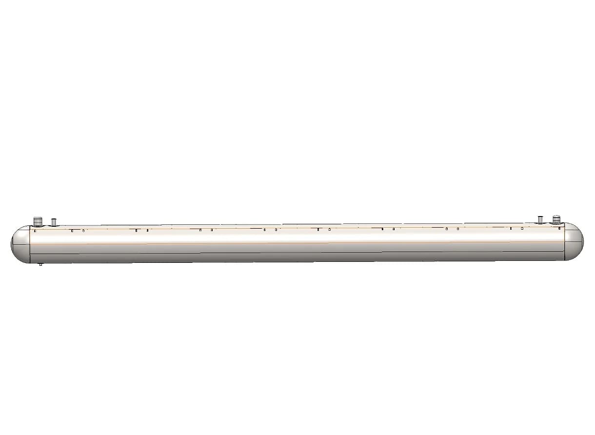
Original CAD view from the consolidated propane report. The shell and repeated internal rings form the main vessel structure
02 Butane Vessel

Original RevD CAD view. The domes, manholes and nozzle regions are retained for detailed assessment
03 Inside the Propane Vessel
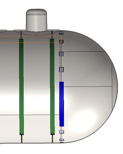
The cutaway exposes the internal stiffeners and the geometry behind the external shell
04 Inside the Butane Vessel
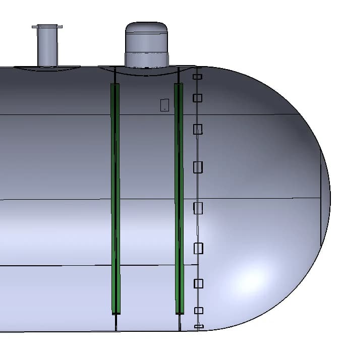
The end-region view shows the shell-to-head transition and local reinforcement around the connections
02 / MODEL DEVELOPMENT
Meshing the shell, openings and stiffeners
The CAD assemblies were prepared for finite element analysis. Full-vessel meshes capture the overall response, while the mesh around penetrations, lifting attachments and internal members resolves the local load paths
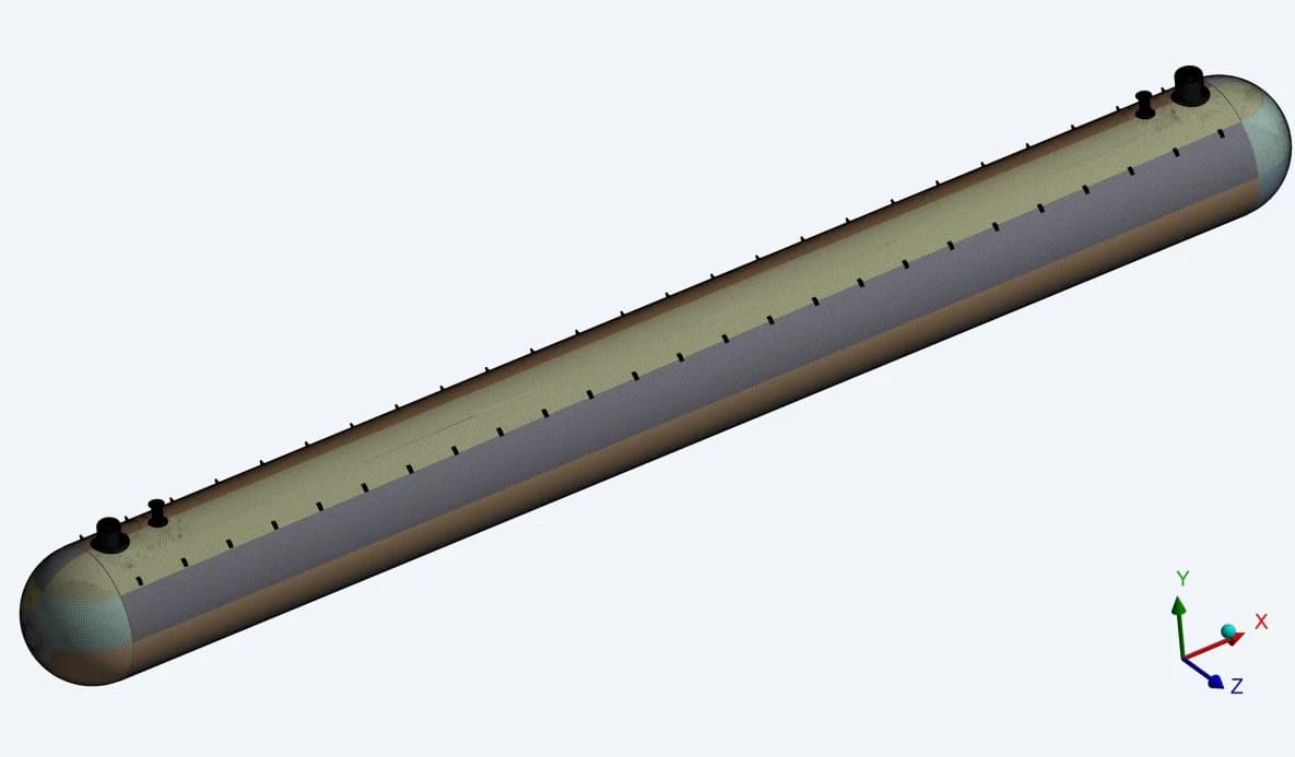
Propane finite element model
The full model represents the shell courses, ends, top connections and attachment regions as one structural assembly
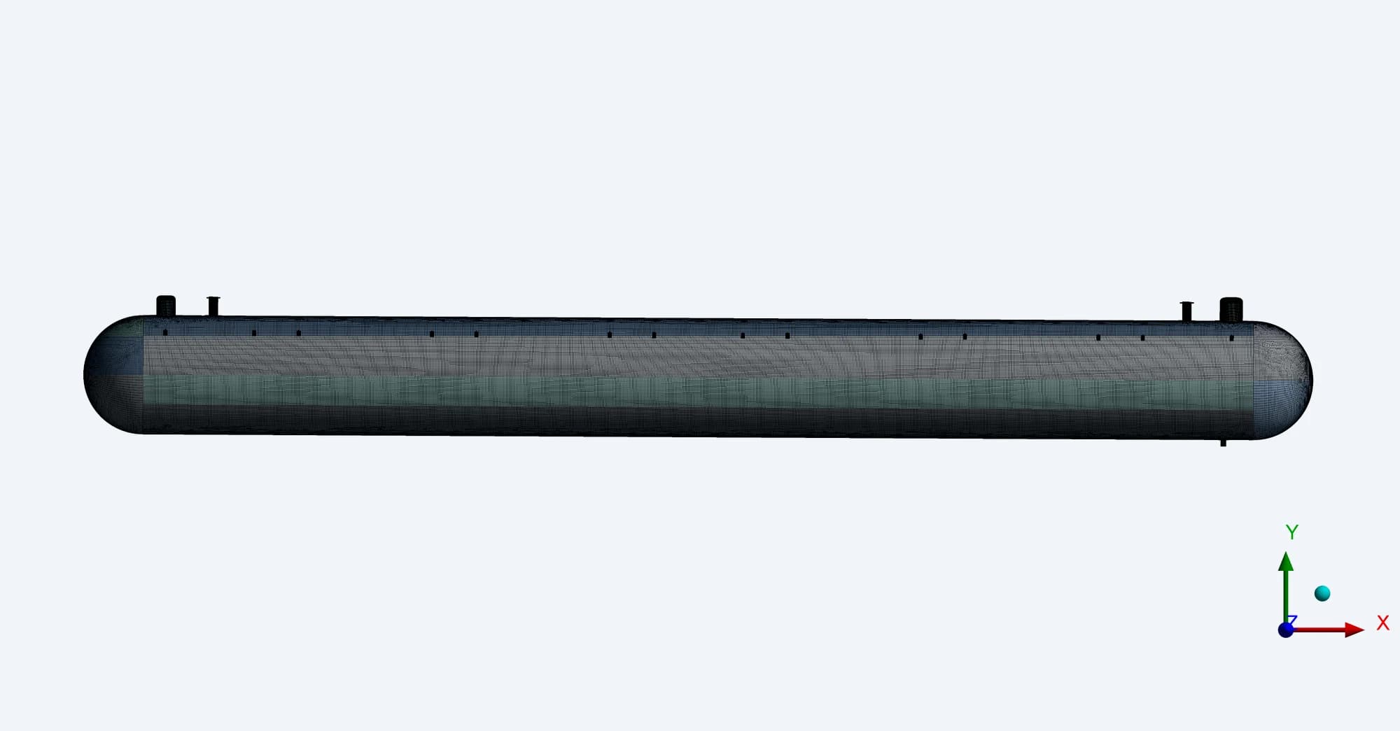
Butane RevD finite element model
The meshed assembly retains the detailed reinforcement and stiffener arrangement used in the pressure assessment
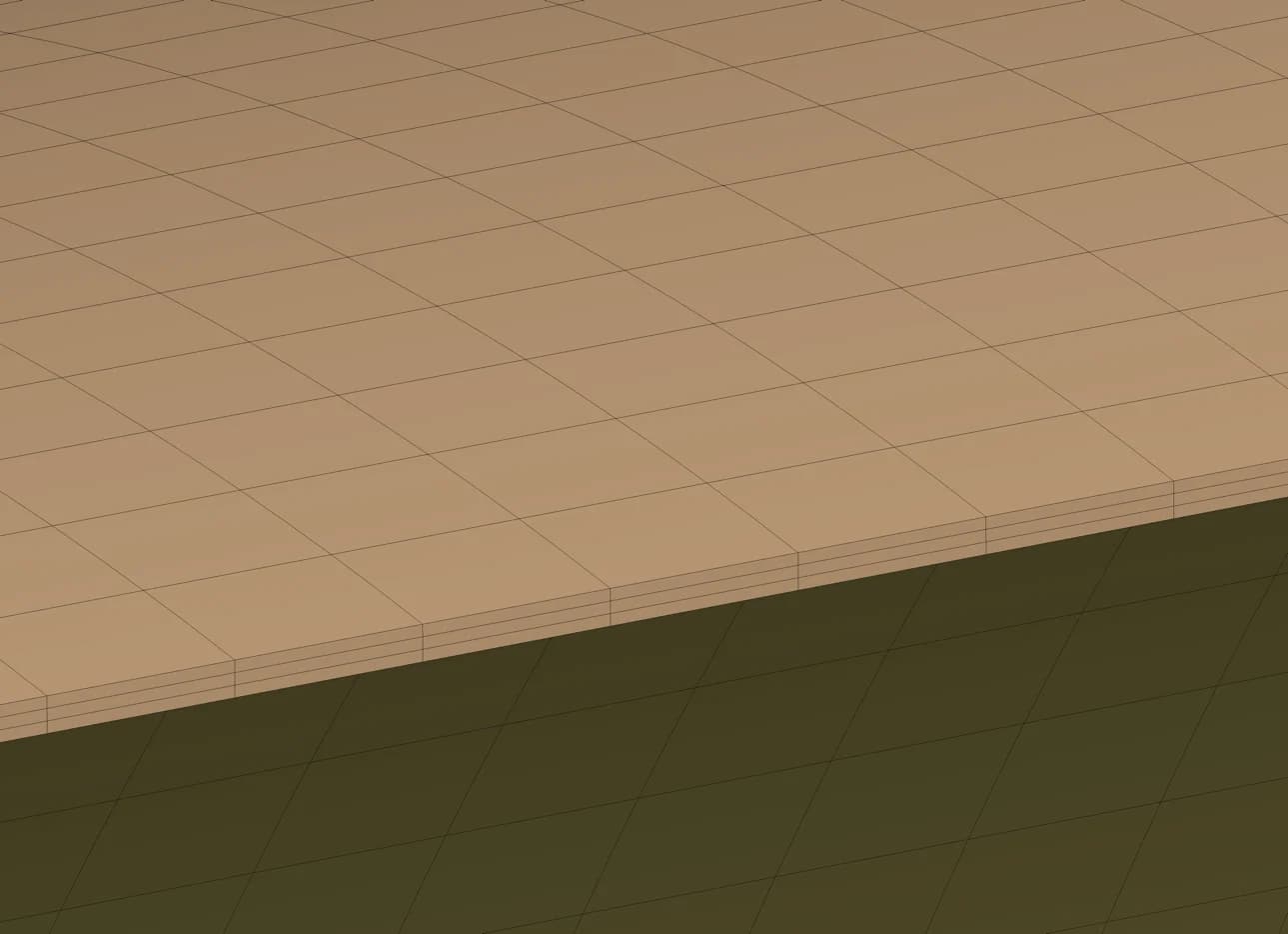
Through-thickness layers
The Butane RevD report specifies three element layers through the shell and head thickness for stress linearization
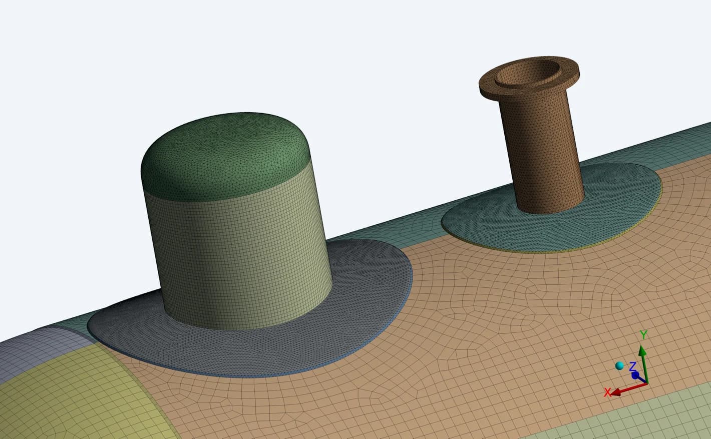
Dome and nozzle interfaces
Local mesh detail represents the changes in shape where openings interrupt the cylindrical shell
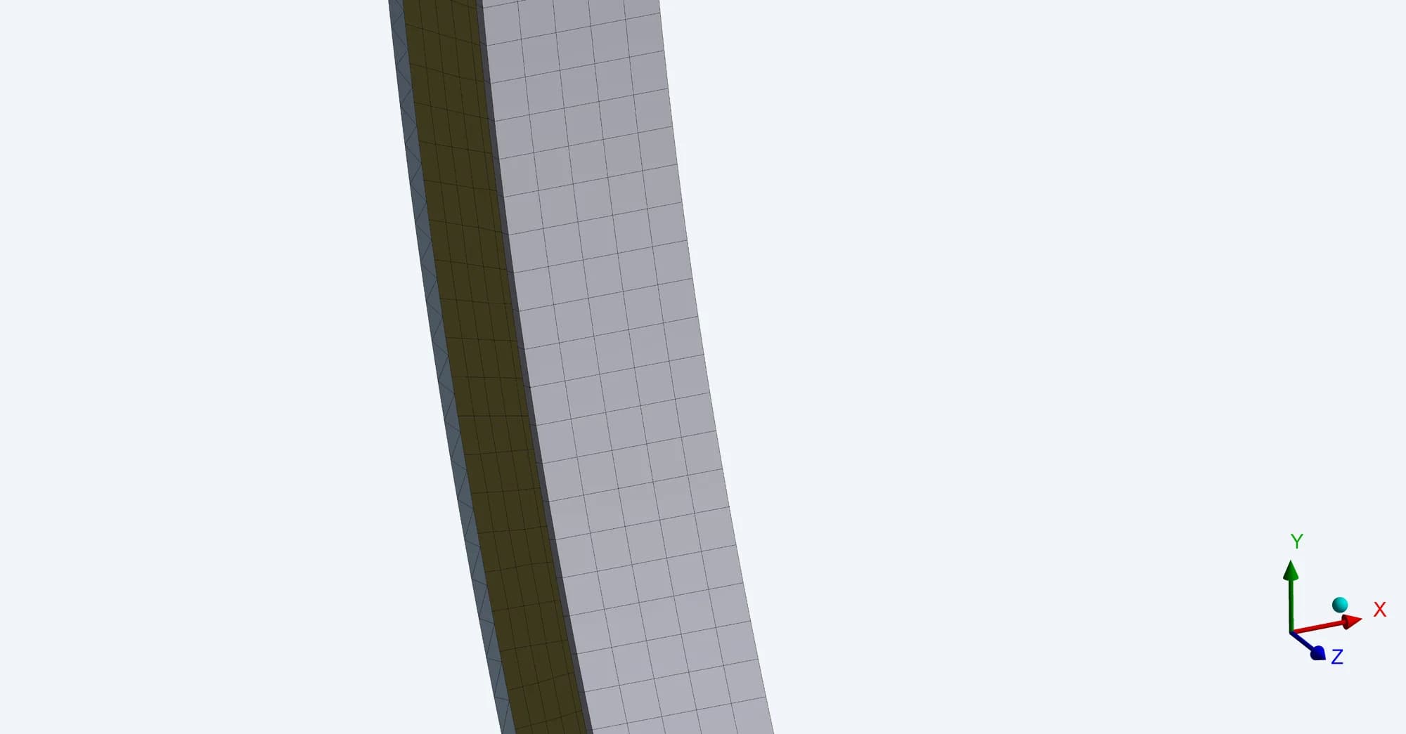
Internal ring stiffeners
Separate ring views make it possible to follow the stress distribution in these internal members
03 / MATERIAL & LOADING BASIS
A programme of distinct loading conditions
The model material is SA 537 Class 1 steel. The reports assume homogeneous material and ideal welded connections. Each load case defines its own pressure, contents, inertia and restraint conditions
- Model elastic modulus
- 203 GPa
- Stated material yield strength
- 344.7 MPa
- RevD design allowable stress
- 137.9 MPa
| STUDY | WHAT THE MODEL EXAMINES | SOURCE BASIS |
|---|---|---|
| Design pressure | Internal / external pressure, fluid head and gravity | Propane + Butane RevD |
| Seismic | Longitudinal and lateral inertia with operating loads | Propane / Butane R2 |
| Hydrotest | Water-filled vessel under the specified test loading | Propane / Butane R2 |
| Support imbalance | Alternative distributions of bedding support | Propane / Butane R2 |
| Section lifting | Self-weight of end and shell sections at lifting lugs | Propane / Butane R2 |
| Higher pressure | Specified pressure multiples in the archived studies | Propane / Butane R2 |
| Gas-cloud loading | Static representation of external overpressure | Propane / Butane R2 |
Propane images use the consolidated Rev00 report for the RevD model. Butane R2 denotes earlier studies; these are not presented as a complete revalidation of the later RevD geometry
04 / DESIGN-PRESSURE ASSESSMENT
Applying pressure and tracing the response
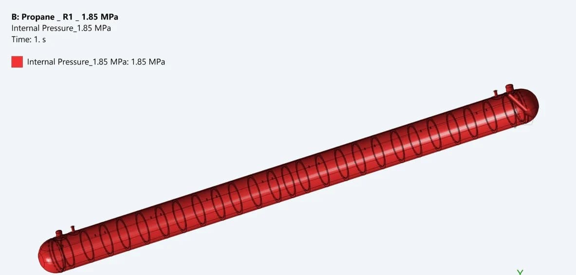
Propane: 1.85 MPa
The case-specific loading definition applies internal pressure to the vessel, alongside the defined external pressure and operating loads
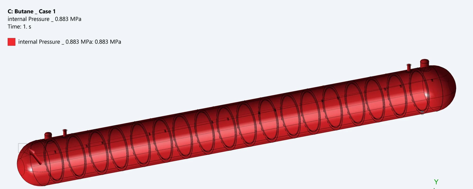
Butane: 0.883 MPa
The RevD model has its own design-pressure basis. The two tanks are assessed against their respective loading definitions
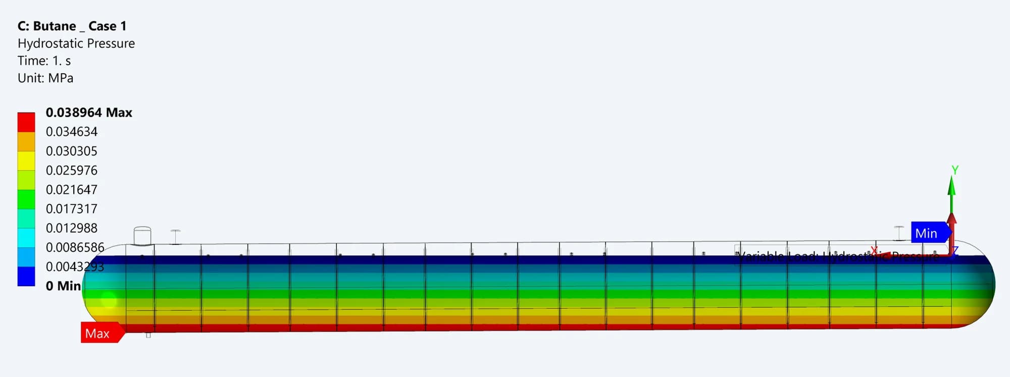
Contents and gravity
The operating setup represents hydrostatic head over 85% of the tank diameter, together with self-weight
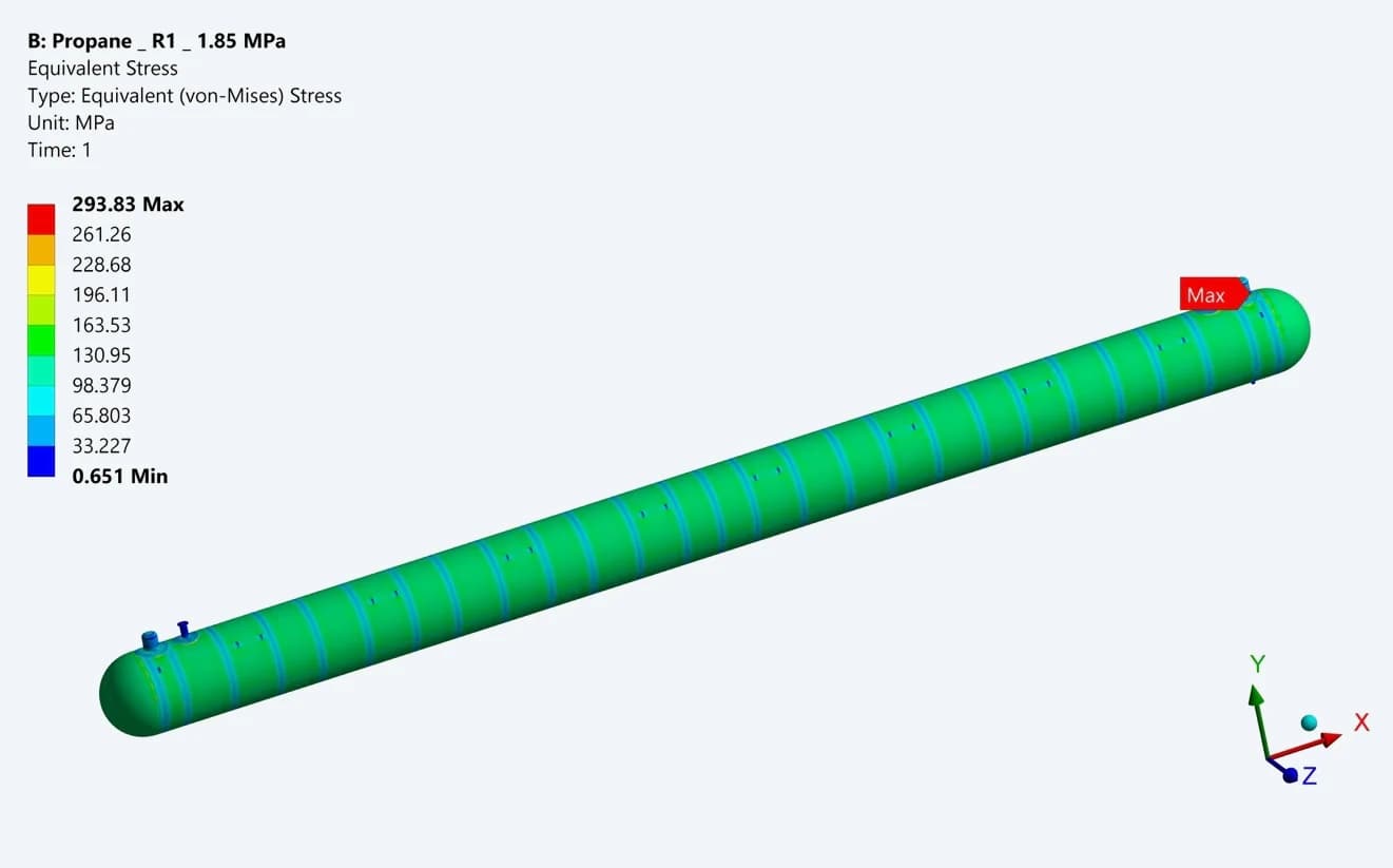
Propane: 293.83 MPa
The original equivalent-stress plot shows the highest local value near the end connections. The shell, rings and openings are then examined separately
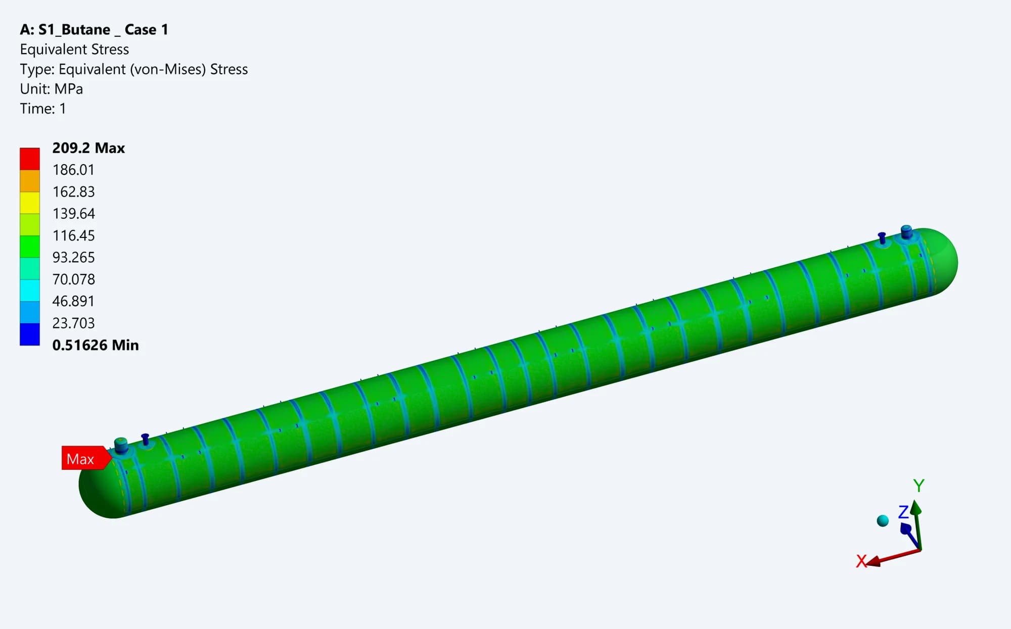
Butane RevD finite element model
The original pressure-case contour identifies the higher-demand region in the revised vessel assembly. Detailed stress-category checks follow
These are local equivalent-stress maxima, not membrane-stress acceptance values. The tanks have different pressure bases, so this comparison does not rank their performance
05 / COMPONENT-LEVEL RESULTS
Looking closely at openings and reinforcement
01 Propane Dome
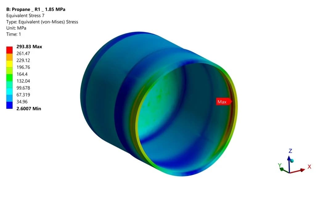
The component view isolates the stress around the dome-to-shell connection under design pressure
02 Propane Manhole
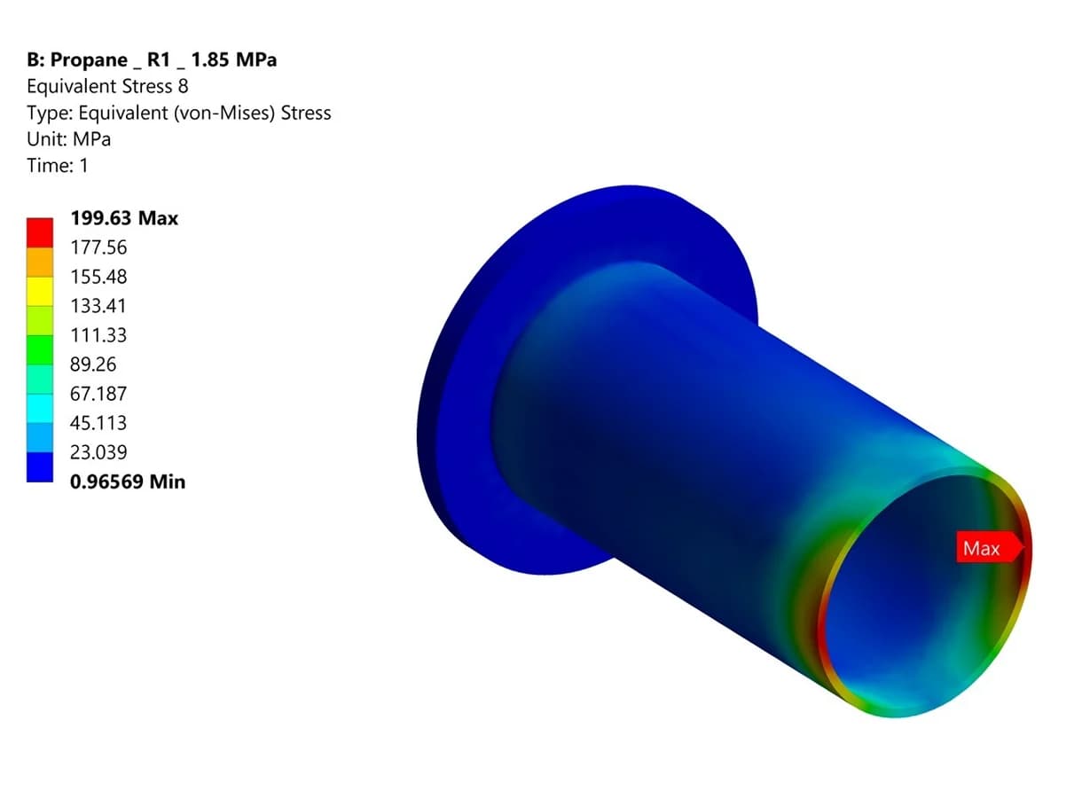
The manhole result shows how stress varies around the penetration and its connection to the vessel.
03 Propane Reinforcement Pad
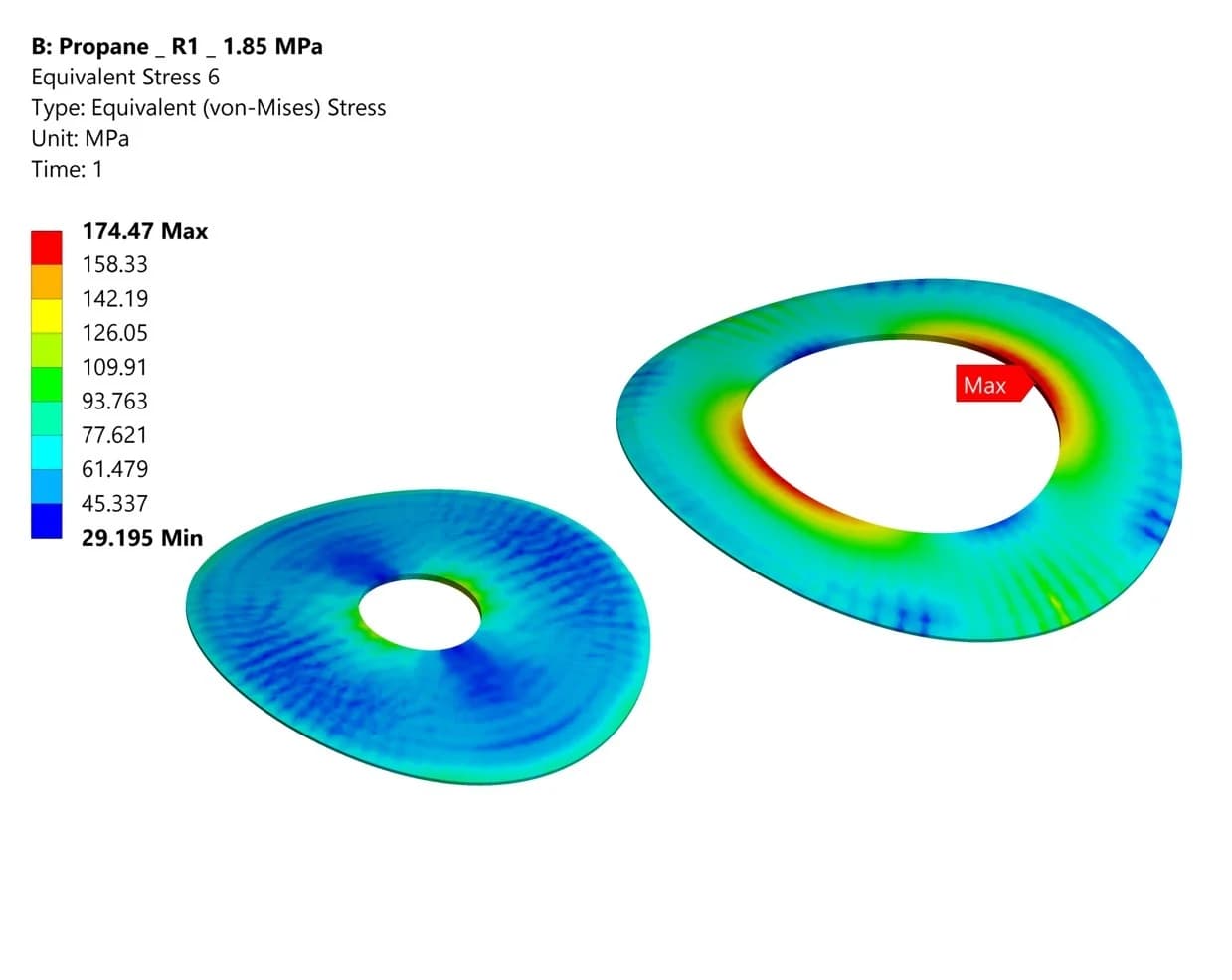
The pad contour identifies local demand around the reinforced opening
04 Butane RevD Dome
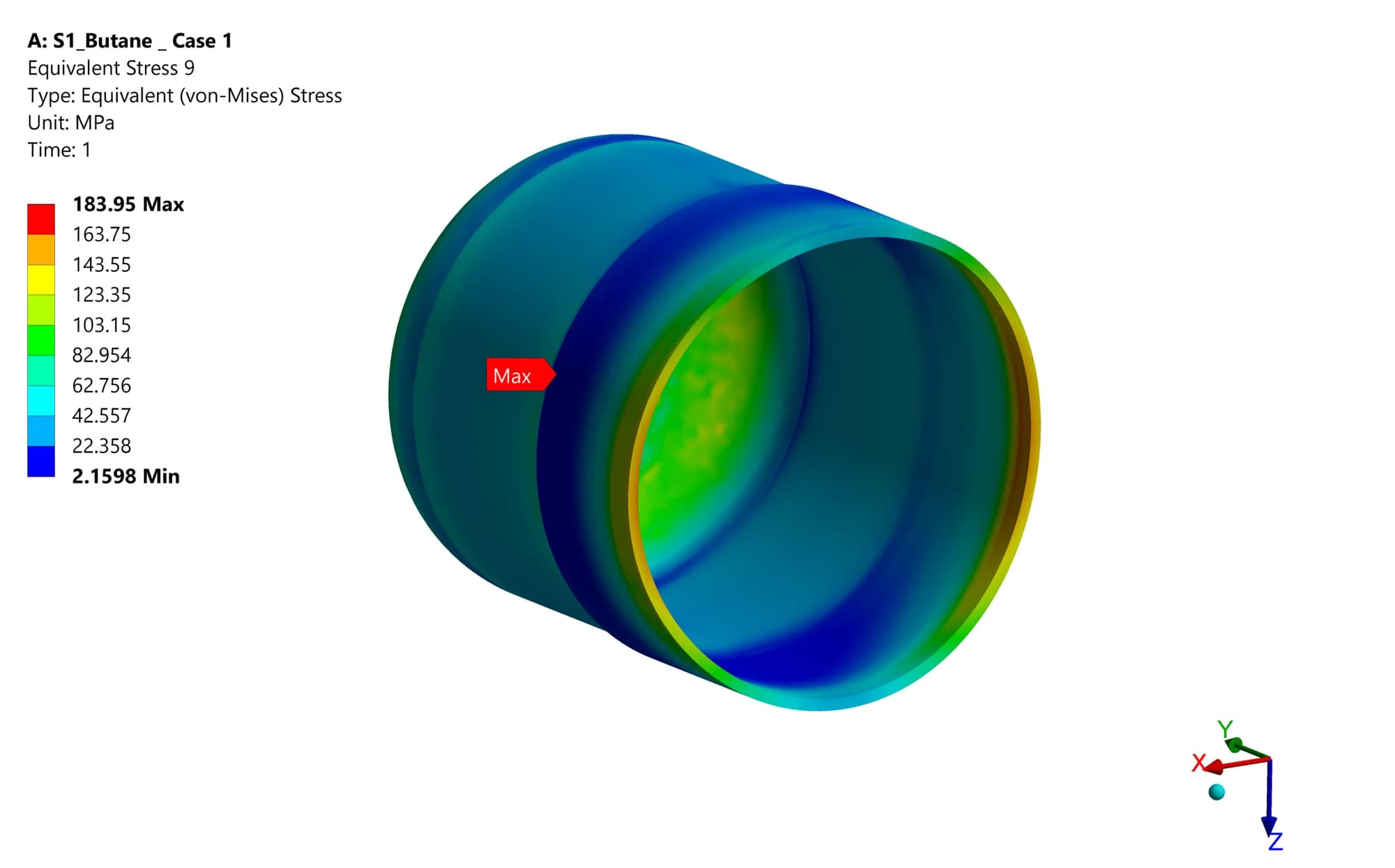
The revised connection is checked as a separate component in addition to the full-tank result
05 Butane RevD Manhole
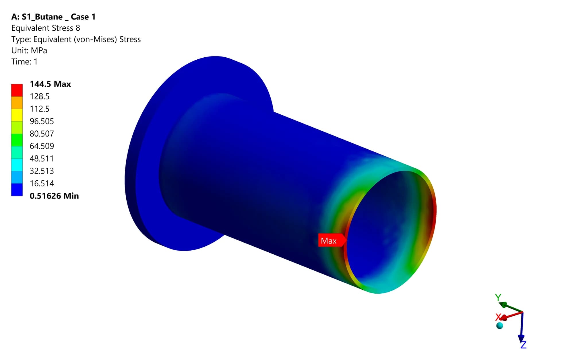
The extracted contour focuses attention on the manhole transition and the local stress pattern
06 Butane RevD Reinforcement Pad
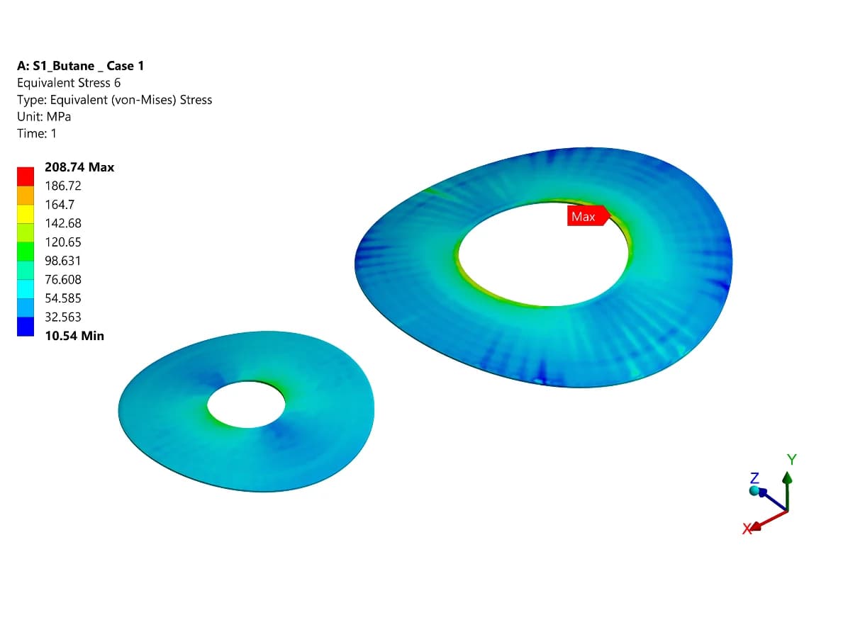
The revised pads are reviewed alongside the adjoining shell and connection geometry
07 Propane Internal Ring
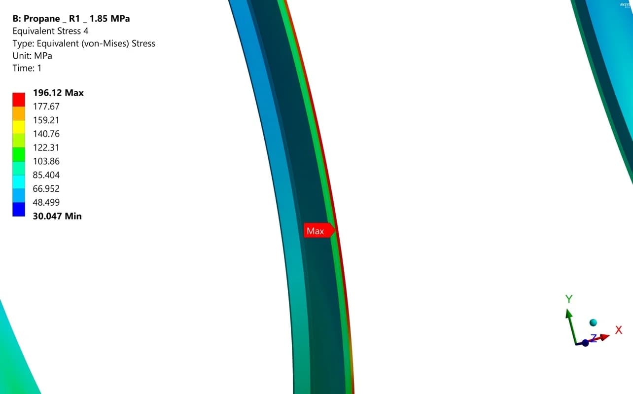
The ring is isolated to show the stress gradient through its section and around its circumference
08 Butane RevD Internal Ring
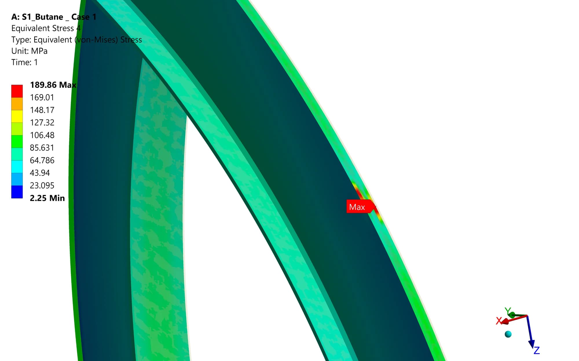
Reviewing the stiffener separately reveals demand that can be difficult to distinguish in a complete-vessel contour
06 / ASME SECTION VIII, DIVISION 2
Design by Analysis using SCL methodology
The assessment uses Stress Classification Lines (SCLs) through the wall thickness at selected shell, dish-end and connection locations. Stress linearization separates membrane and bending response for evaluation against the ASME Section VIII, Division 2 criteria cited in the reports
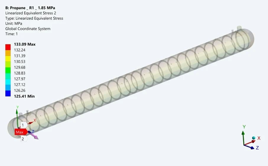
Propane dish-end path
The SCL crosses the wall at a selected high-stress location. The thickness-average membrane response and linear bending component support the stress-category assessment
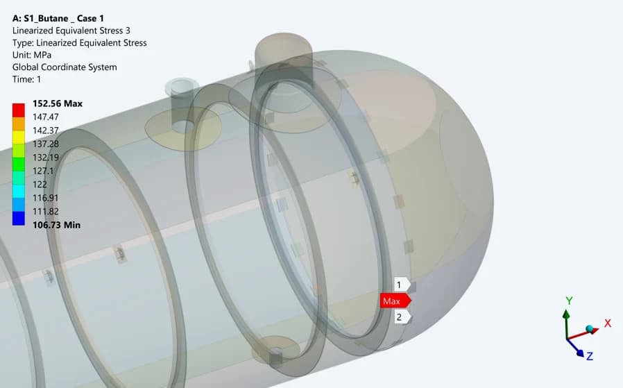
Butane RevD dish-end path
The revised geometry has corresponding SCL checks. Membrane and membrane-plus-bending results are compared with the limits for the assigned stress category and loading condition
| DESIGN PRESSURE PATH | MEMBRANE / MPa | MEMBRANE + BENDING / MPa |
|---|---|---|
| Propane dish end | 128.97 | 133.09 |
| Propane mid-shell | 126.86 | 132.43 |
| Butane RevD dish end | 123.66 | 151.74 |
| Butane RevD mid-shell | 105.60 | 119.36 |
| Butane RevD dome | 121.96 | 167.60 |
Selected equivalent-stress values from the detailed tables; membrane + bending uses the larger reported surface value. The reports record satisfaction of the applicable checks for these paths. Their stated general membrane limit is 137.9 MPa; the corresponding combined limit is 206.85 MPa.
07 / DOCUMENTED DESIGN DEVELOPMENT
Refining the butane connection geometry
The Butane RevD report records changes to the reinforcement pads, dome thickness and shell-to-dish-end stiffeners. These details show how the structural assessment was carried into a revised geometry for evaluation
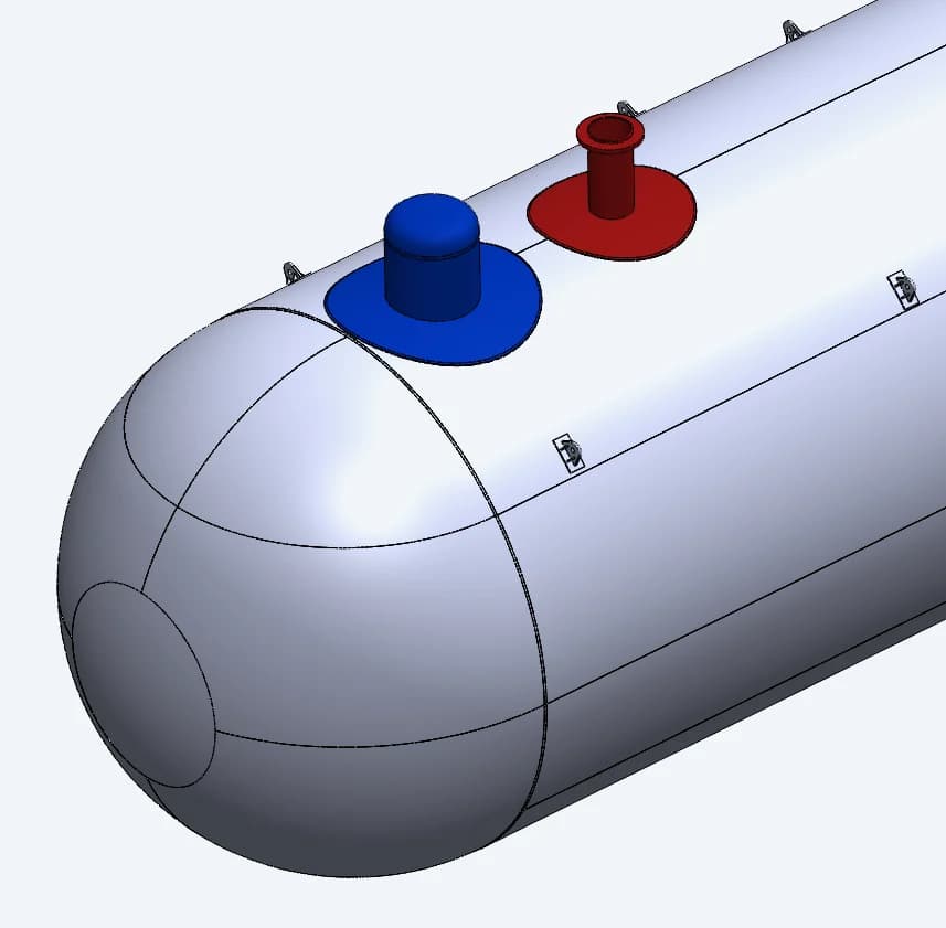
Reinforcement pads
Recorded pad diameters: dome 2,950 mm, manhole 2,300 mm and N2 nozzle 1,280 mm. A 1:3 chamfer provides the specified transition
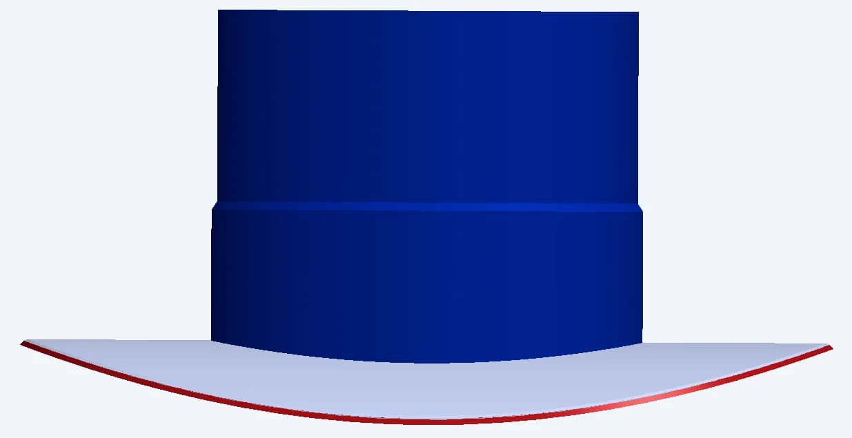
Dome wall thickness
The documented dome arrangement uses a 38 mm lower ring and a 20 mm upper ring
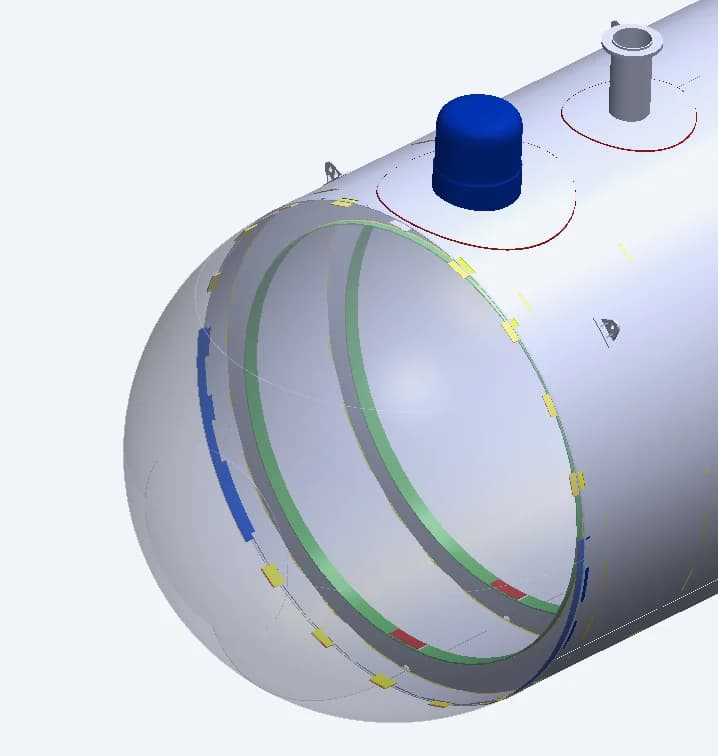
Shell-to-head stiffeners
The revision adds the detailed stiffener arrangement at the shell-to-dish-end junction, including 20 mm-thick plates
08 / SEISMIC STUDIES
Examining response in two directions
The archived seismic cases apply 0.15 g acceleration longitudinally and laterally. Changing direction changes the way inertia is carried by the shell, internal stiffeners and connection regions
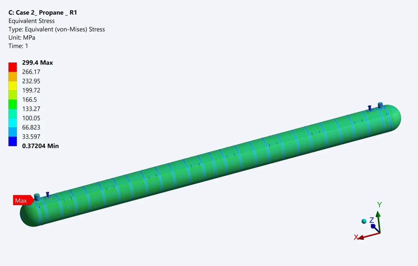
Propane: longitudinal stress
The longitudinal seismic case reports a local equivalent-stress maximum of about 299.4 MPa in the consolidated study
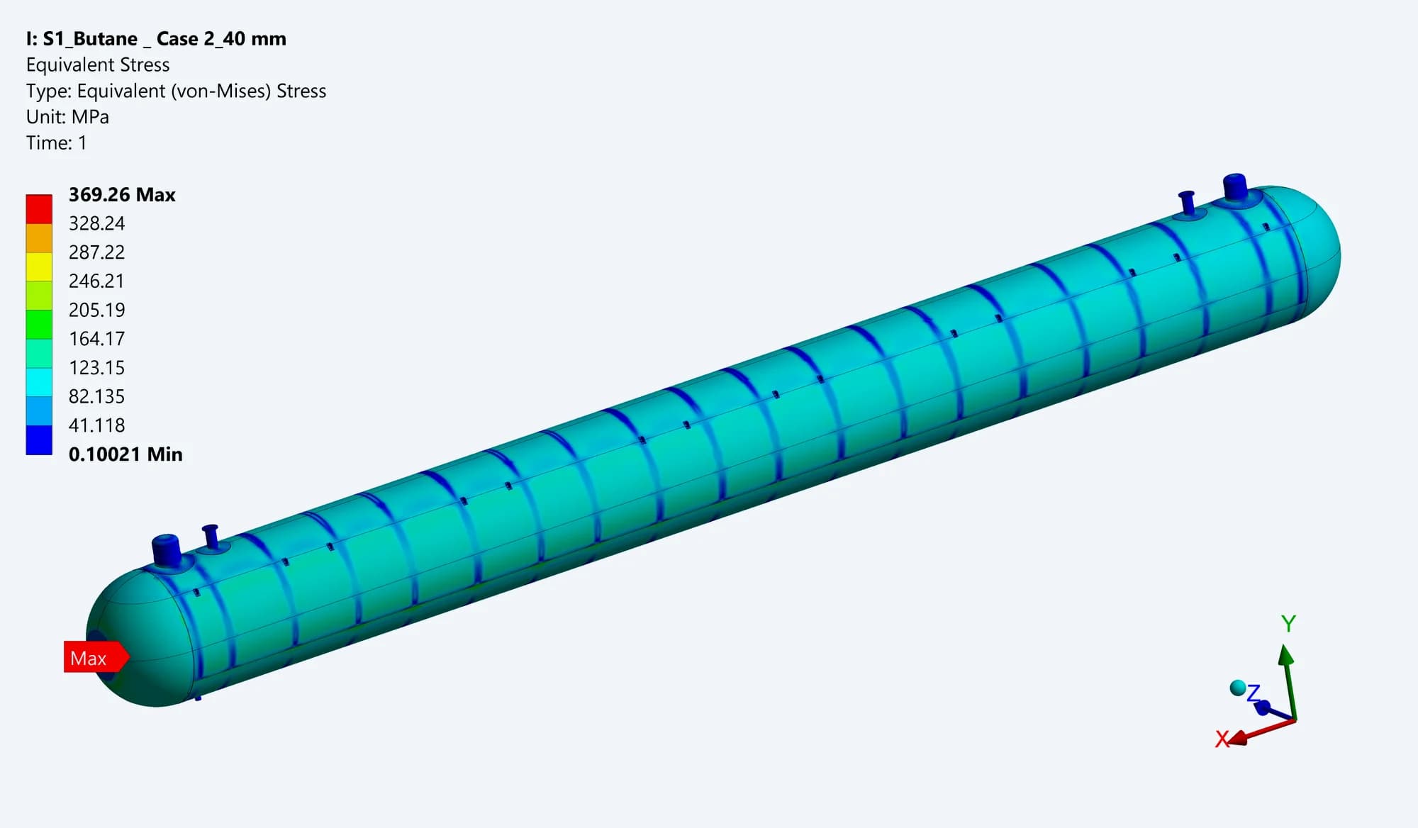
Butane R2: longitudinal stress
The earlier butane model shows a 369.26 MPa local maximum. This result belongs to the R2 study and is not a RevD acceptance result
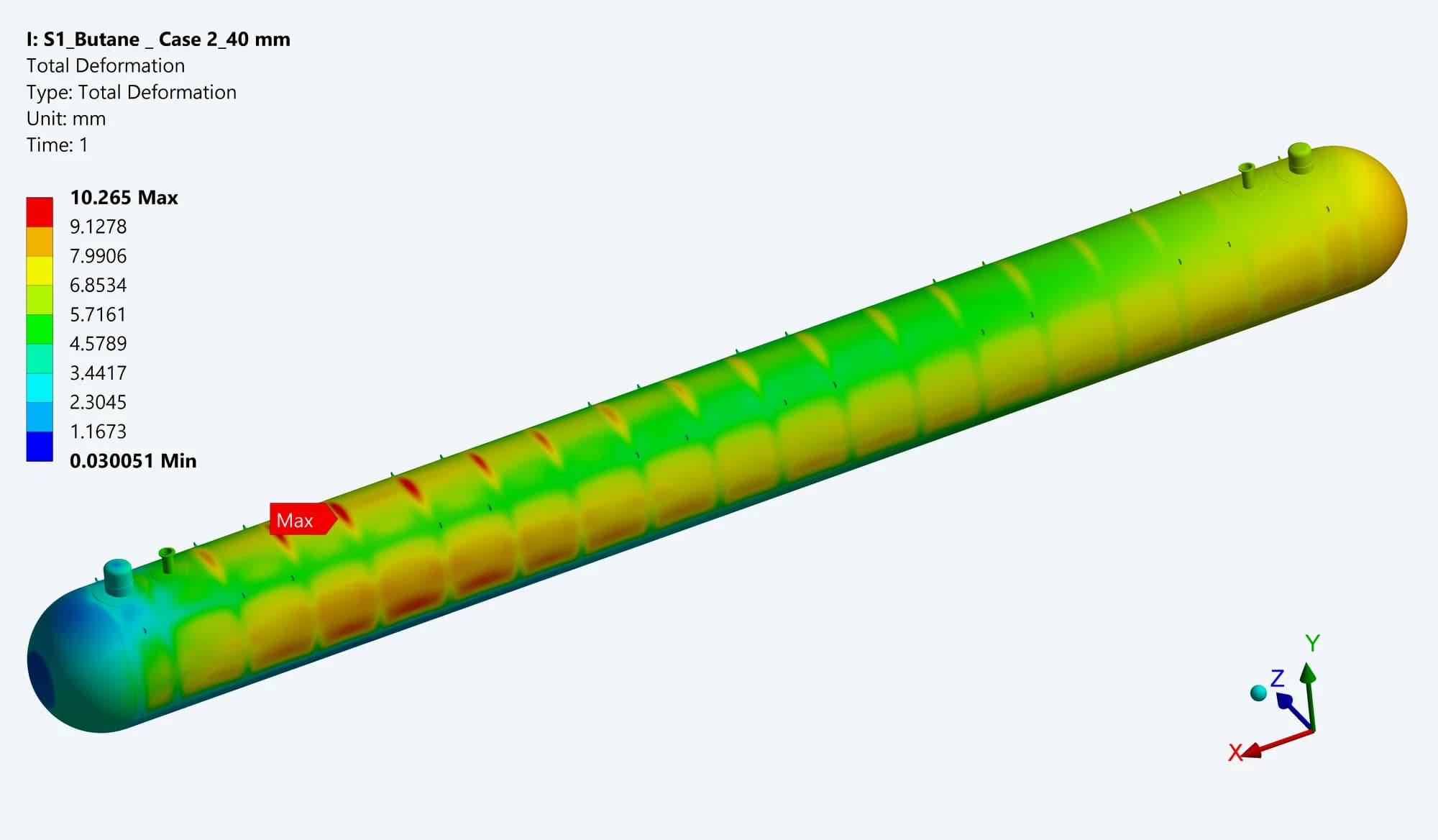
Butane R2: longitudinal movement
The original plot shows 10.265 mm maximum total deformation, with movement distributed along the shell and between the internal rings
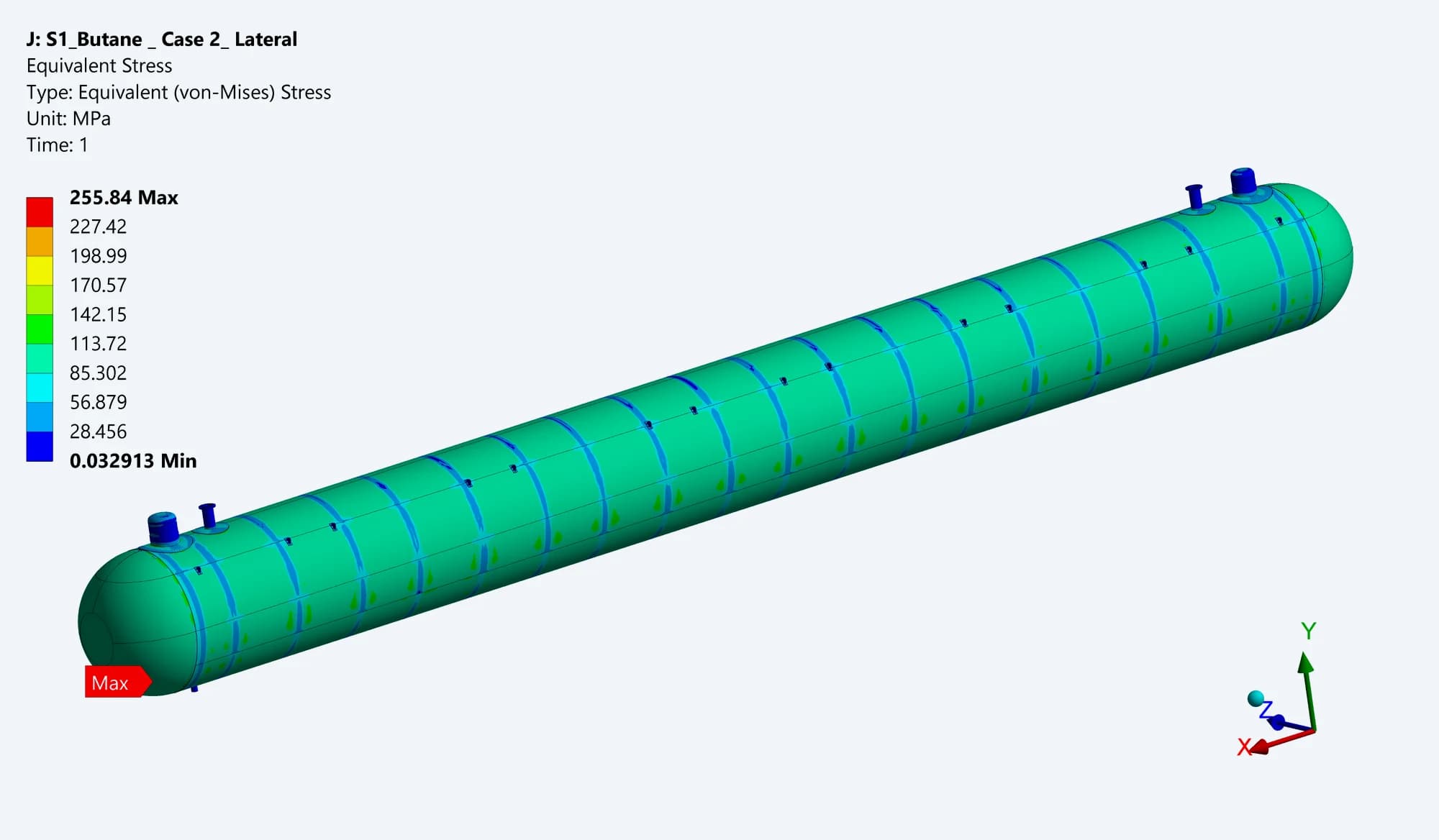
Butane R2: lateral stress
The lateral contour shows 255.84 MPa maximum equivalent stress. The change in direction alters both the stress distribution and the locations carrying higher demand
09 / HYDROTEST ASSESSMENT
Checking the water-filled test condition
The hydrotest models represent a fully water-filled vessel and the specified test loading. The change in contents and pressure produces a different stress distribution, which is examined through complete-vessel contours and detailed component checks
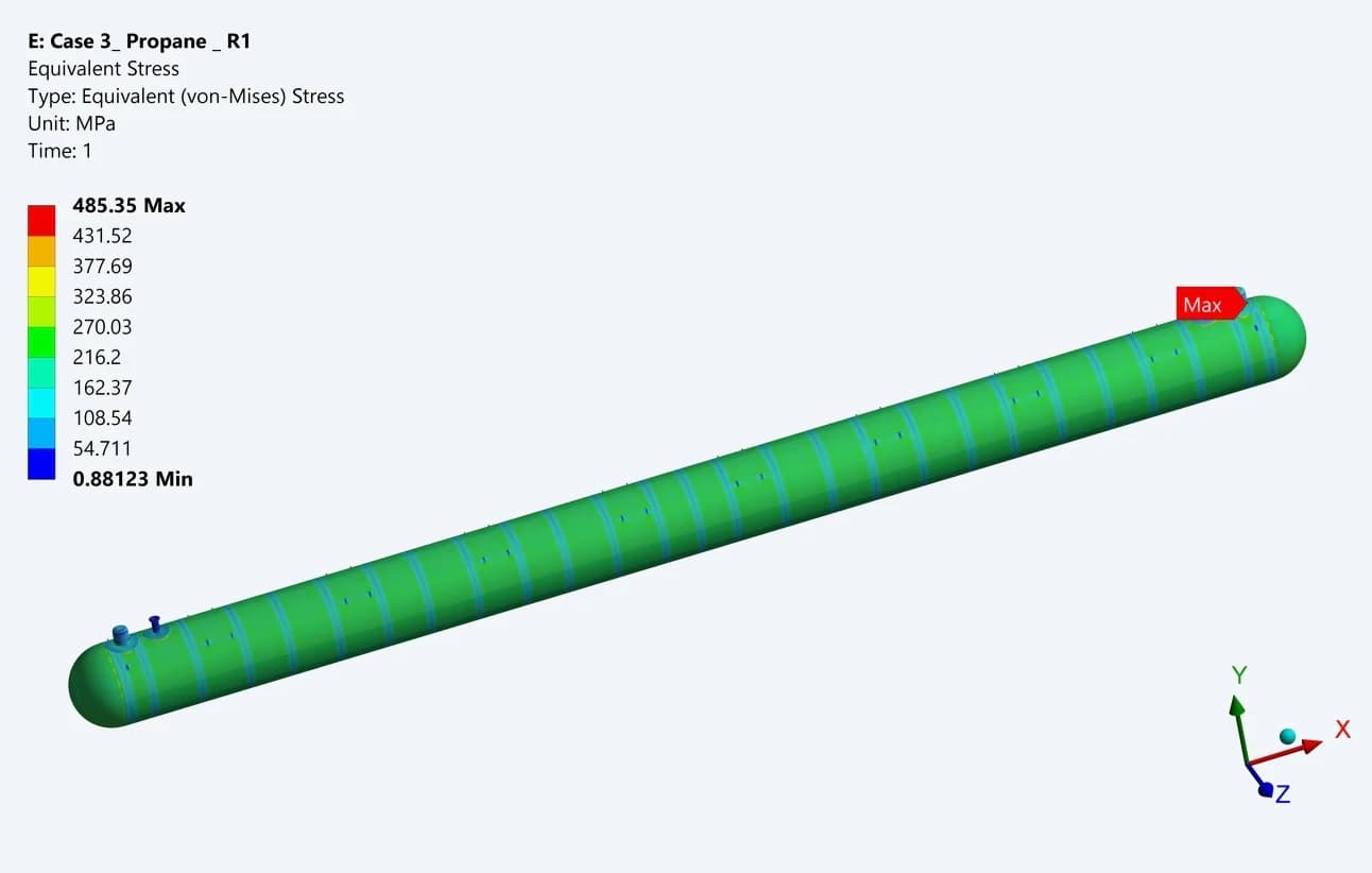
Propane hydrotest study
The original equivalent-stress contour reaches 485.35 MPa locally. The report also examines selected stress-linearization paths under its test-condition criteria
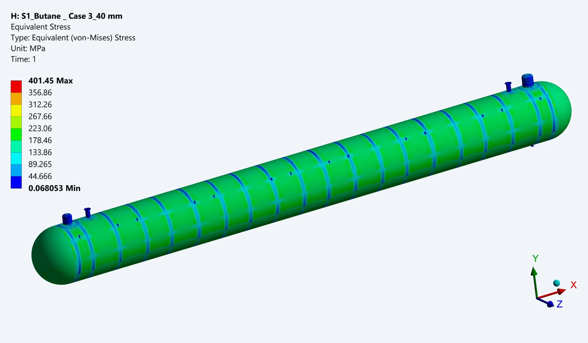
Butane R2 hydrotest study
The earlier butane contour reaches 401.45 MPa locally. The separate study traces the demand through the shell, ends, stiffeners and openings
These plots are analysis outputs, not physical hydrotest records. Local peaks exceed the stated material yield strength and require the report’s stress-category and modelling context; they do not establish an unrestricted pass
10 / BEDDING & SUPPORT IMBALANCE
Testing alternative support distributions
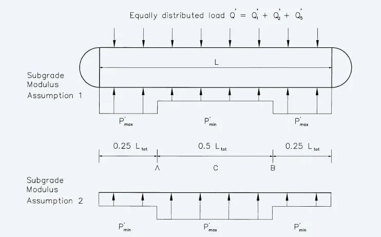
Two support assumptions
The archived diagrams vary support along the vessel length to represent alternative subgrade distributions
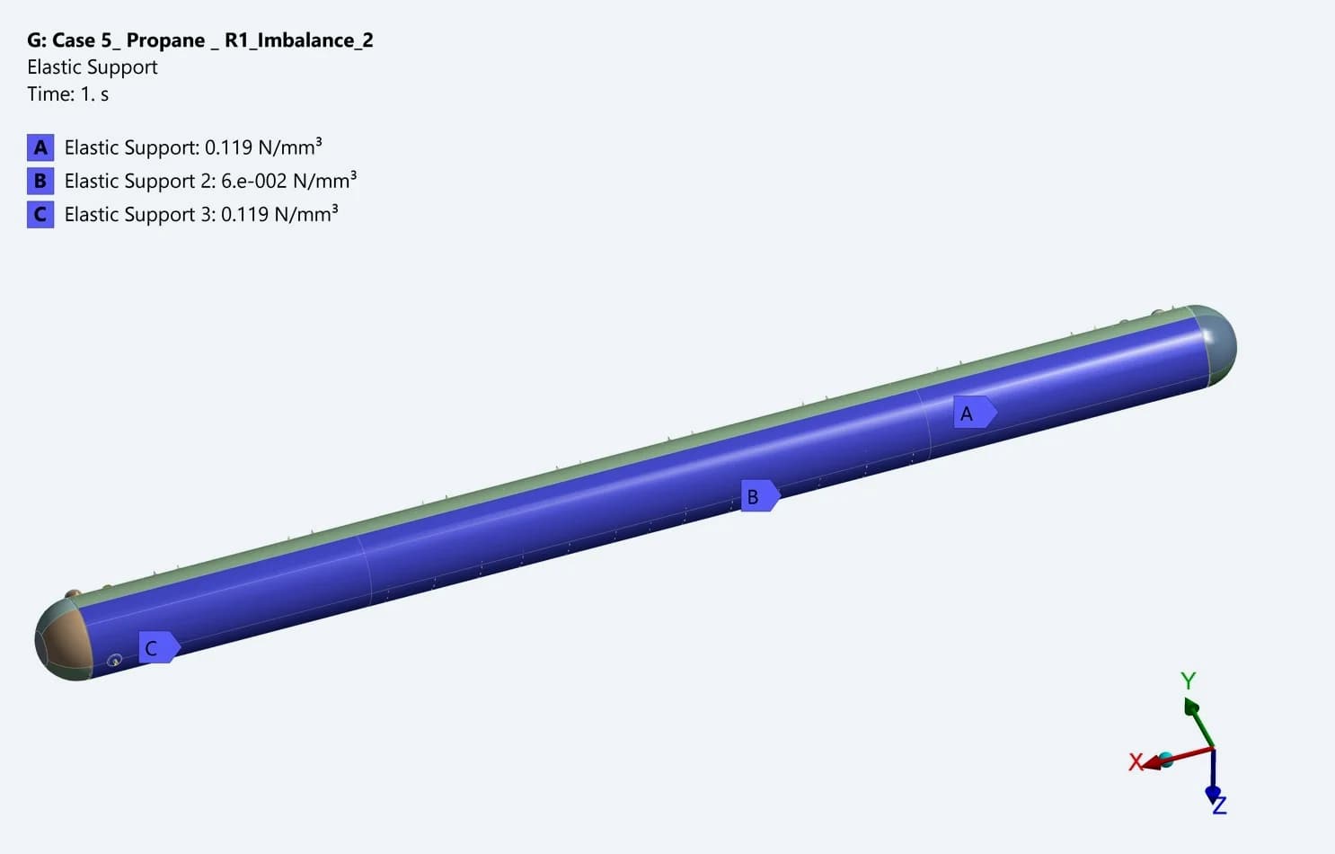
Applying the support to the FE model
The model assigns different support values along the lower shell. This tests the sensitivity of the vessel to the assumed bedding response
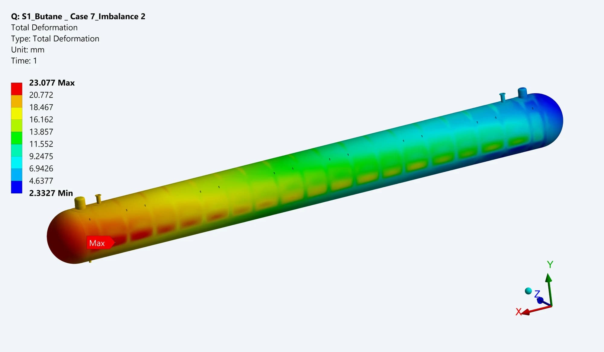
Butane R2: first arrangement
The first displayed support arrangement gives about 23.08 mm maximum total deformation. The local movement follows the changed support distribution
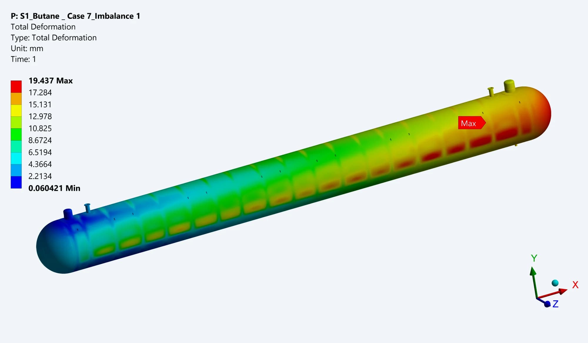
Butane R2: second arrangement
The second arrangement gives about 19.4 mm maximum total deformation. Both the displacement pattern and component stresses were reviewed
The propane study also includes two support-imbalance conditions. These are prescribed support scenarios; they are not site settlement measurements or a geotechnical verification
11 / SECTION-LIFTING ASSESSMENT
Following the handling loads through the lugs
Separate models assess an end section with its dome and a cylindrical shell section under self-weight. Restraints at the lifting attachments change the load path, placing particular emphasis on the lug, pad and adjacent shell
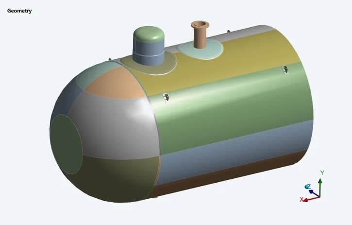
End section with dome
The original propane model includes the dish end, a length of shell, internal rings and top connections
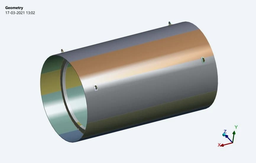
Cylindrical shell section
The shell-only model has its own attachment positions and local response. These are partial-section studies
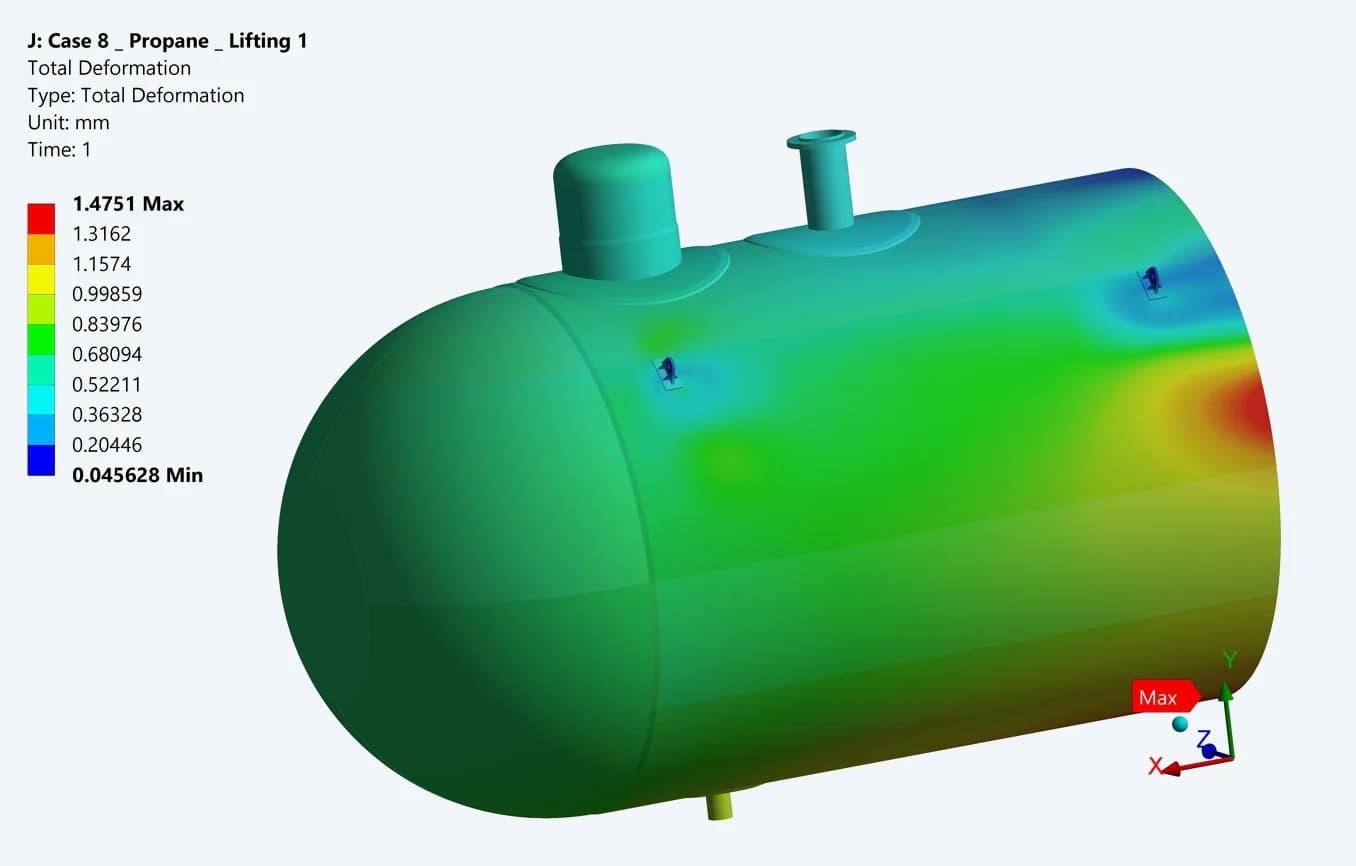
Propane end-section movement
The source plot reports about 1.5 mm maximum total deformation for the modelled lifting condition
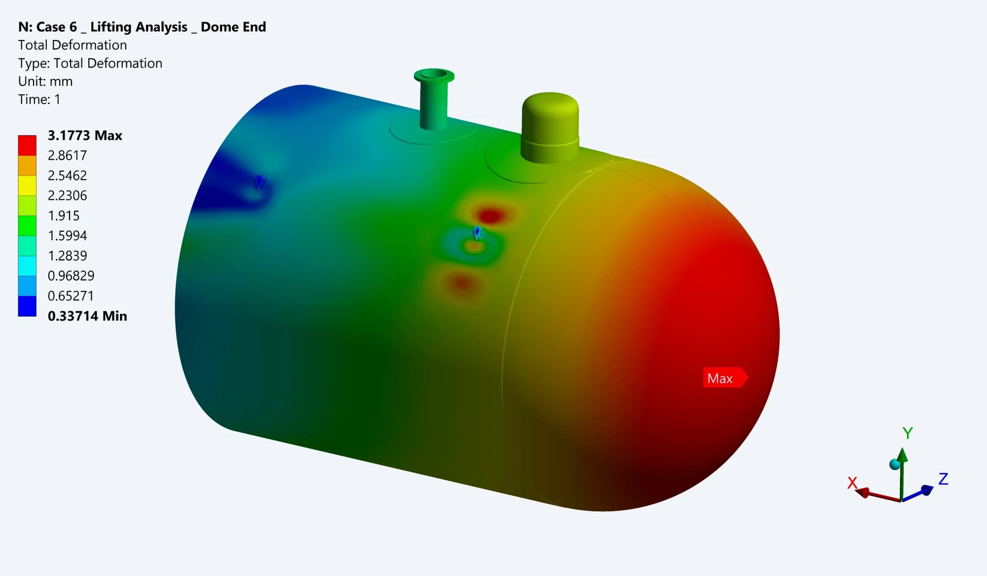
Butane R2 end-section movement
The original contour reports 3.18 mm maximum total deformation. The open shell edge and attachment regions show distinct movement
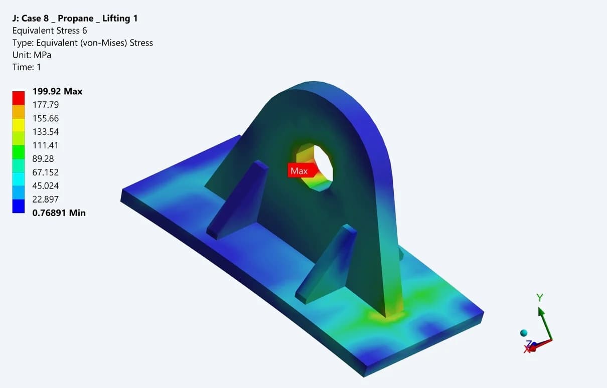
Propane lifting lug
The isolated attachment plot shows approximately 200 MPa local equivalent stress for the end-section lifting case
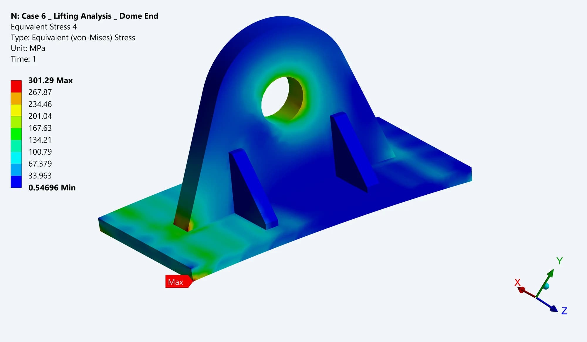
Butane R2 lifting lug
The earlier butane attachment result shows 301.29 MPa locally. The report also reviews the adjoining shell and internal rings
These results apply to the modelled sections, self-weight and restraint assumptions. They do not describe a complete-vessel lift or an approved site rigging procedure
12 / HIGHER-PRESSURE STUDIES
Exploring the specified pressure scenarios
The archive includes studies labelled burst-pressure analysis. The propane report examines a 2.5-times-MAWP case; the earlier butane study includes 2.5-times and 4-times cases. MAWP is maximum allowable working pressure
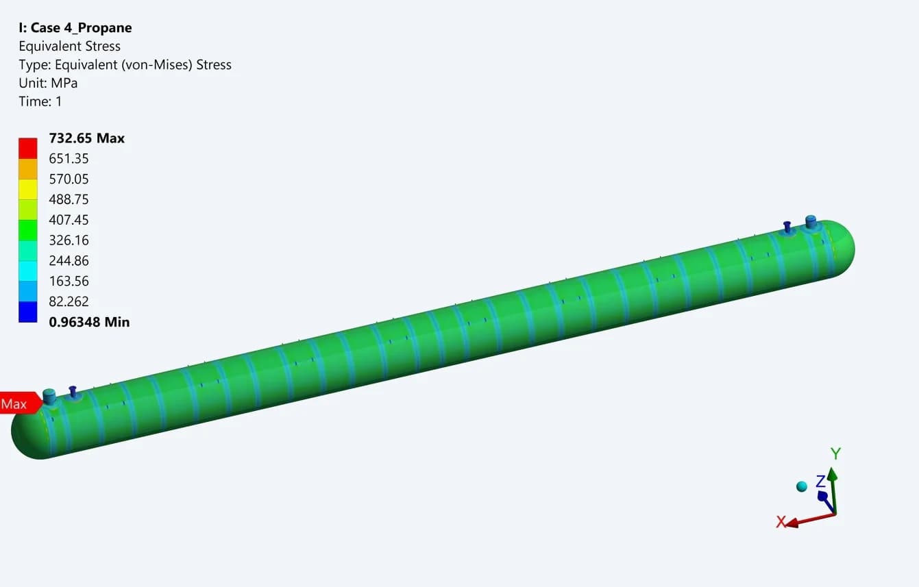
Propane: 2.5-times case
The original contour reports 732.65 MPa local equivalent stress under the prescribed higher-pressure loading
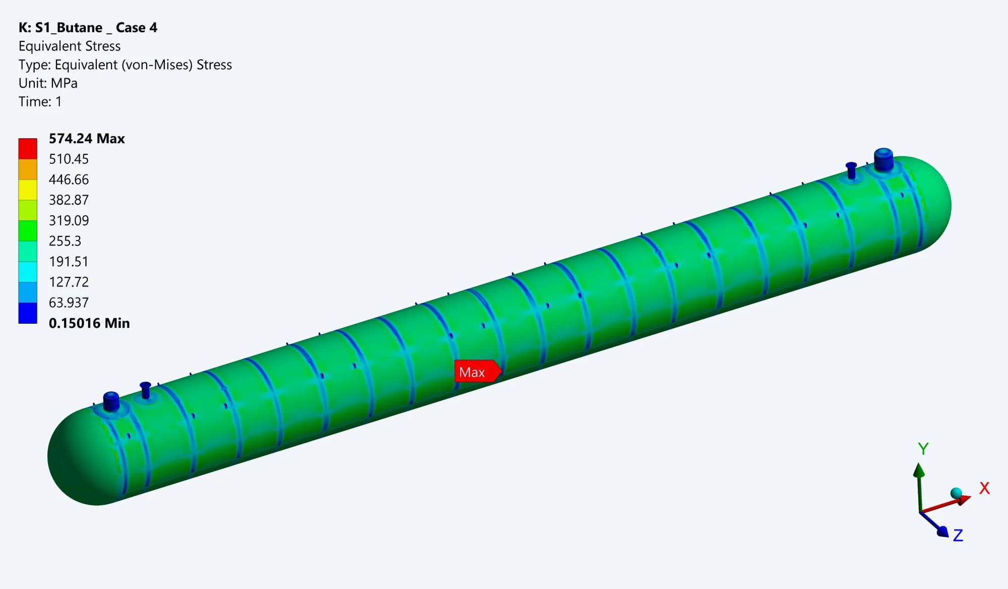
Butane R2: 2.5-times case
The selected contour reports 574.24 MPa. The archive also contains a separate 4-times pressure scenario
These are applied-load studies, not measured burst pressures. The reported peaks exceed the material yield strength; the plots alone cannot establish actual failure pressure or a usable capacity margin
13 / EXTERNAL OVERPRESSURE
Assessing a gas-cloud loading scenario
The project extends the assessment to a gas-cloud loading case represented as static external overpressure, with the defined mound and gravity loads. The component results show where that assumed loading is carried within each vessel
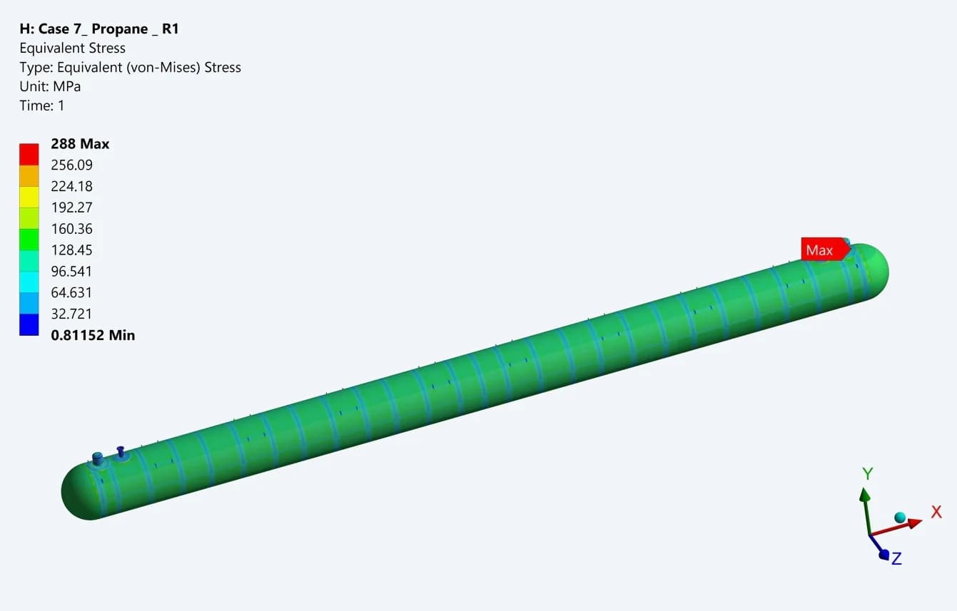
Propane static-overpressure study
The displayed contour reports approximately 288 MPa local equivalent stress. The report reviews the shell, rings and top connections separately
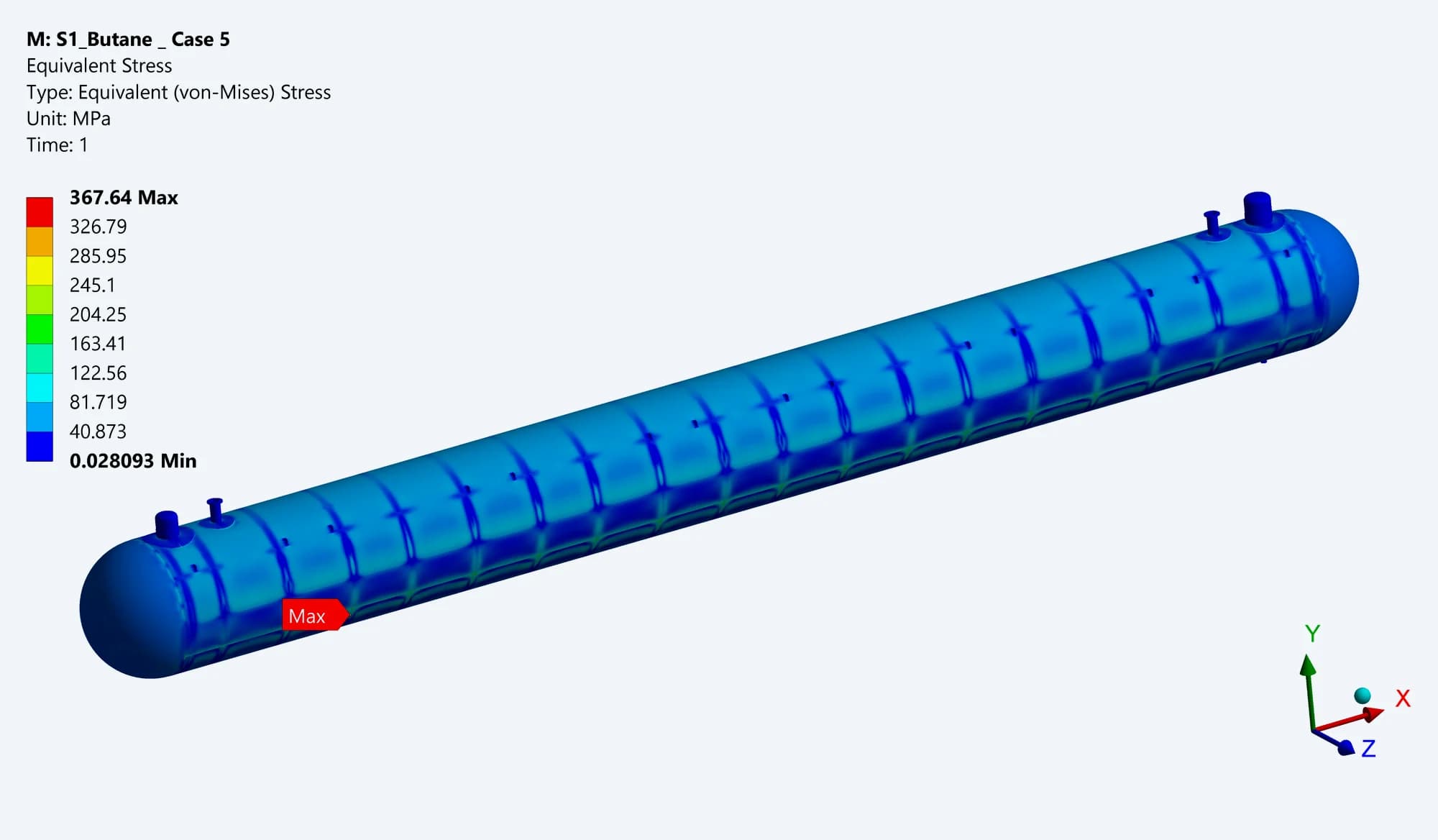
Butane R2 static-overpressure study
The earlier model shows 367.64 MPa locally, with the ring-stiffener response examined in separate component plots
The archived setup is a static structural representation. These results do not represent a time-resolved blast simulation or an experimentally demonstrated explosion rating
14 / ENGINEERING FINDINGS
Connecting the analysis to design decisions
| ENGINEERING QUESTION | WHAT THE WORK ESTABLISHED |
|---|---|
| Pressure response | Full-vessel and component stress patterns for both design-pressure bases. |
| Local connection demand | Separate assessment of domes, manholes, pads and internal rings. |
| Stress classification | ASME VIII-2 SCL evaluations, with selected through-thickness checks recorded as satisfied in the reports |
| Geometry development | Documented Butane RevD pad, dome and end-stiffener changes |
| Other loading conditions | Response under seismic, hydrotest, support variation, section lifting and prescribed overpressure scenarios |
The study records an engineering assessment across multiple revisions. Earlier R2 findings remain identified by their source; no claim of physical testing, commissioning or complete-vessel certification is made
A detailed basis for vessel design review
The ASME Section VIII, Division 2 assessment connected full-vessel response with the behaviour of individual pressure-boundary components. SCL evaluations resolved membrane and bending stresses at critical regions and supported the documented design development The delivered analysis package gave the engineering team a traceable basis for reviewing the propane and butane vessels across the defined operating, test and handling scenarios