
EV Battery Pack 60V / 39Ah
Understanding the vibration and shock response
finite element analysis
EV Battery Pack
- Requirement
Structural response under road loads
Cygni Energy needed a structural assessment of its EV battery pack under specified vibration and shock conditions, with results for the assembly and critical components
- Challenge
A complete view of the load path
We needed to represent the cell-pack mass and support conditions, then locate stress concentrations in the mounting plates and enclosure parts under Y and Z loading
- Deliverables
Four documented FEA studies
Our work covered model preparation, meshing, boundary conditions and result interpretation. Four reports documented Y and Z harmonic response and shock analysis
- Battery pack specification
- 60 V / 39 Ah
- Reported vibration study range
- 7–200 Hz
- Harmonic and shock cases
- 4
MECHANICAL DEVELOPMENT
The structure and its internal assemblies
01 CAD preparation
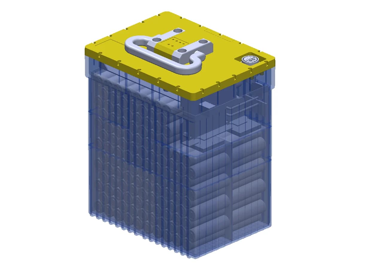
Original CAD view of the battery pack assembly
We used the supplied assembly geometry to define the enclosure, lid and mounting hardware, with the internal cell arrangement visible in the CAD model
02 Finite element mesh
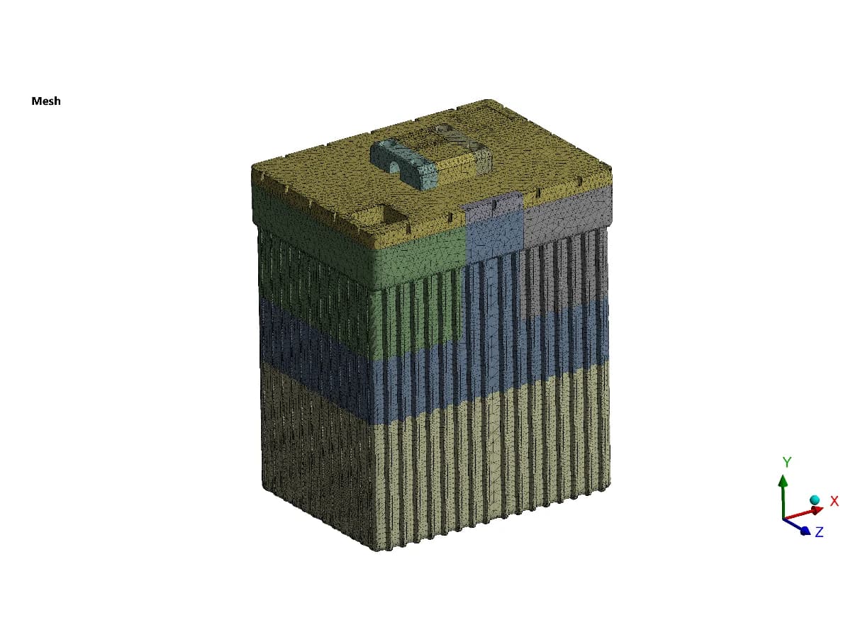
Original mesh image from the project working files
We meshed the geometry to calculate deformation and stress across the pack, including the enclosure details and mounting interfaces
03 Supports and load cases
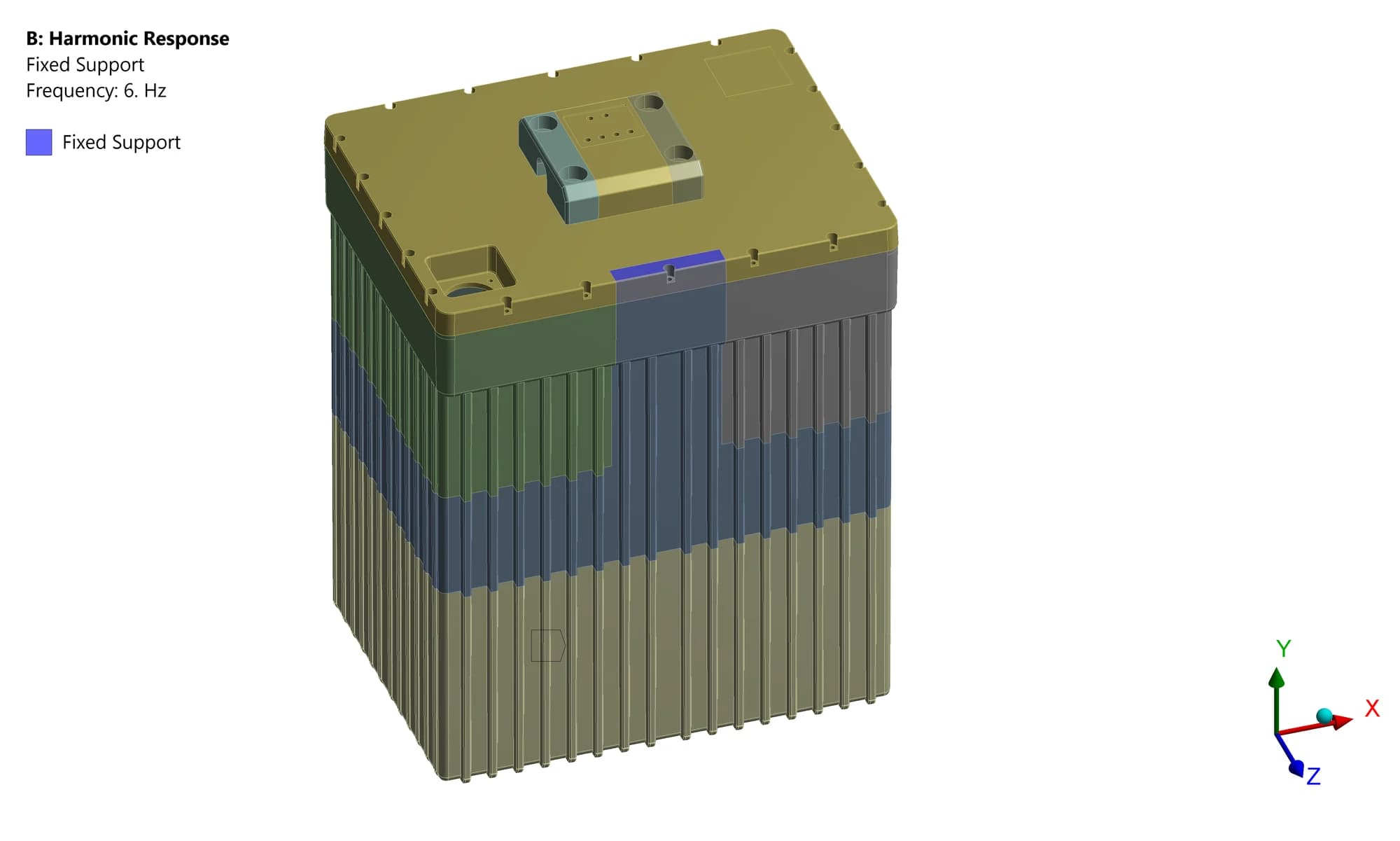
Fixed support definition in the analysis model
We defined mounting constraints and Y and Z vibration and shock cases. The reports reference AIS-156 Annex 8A for boundary conditions
04 Cell-pack mass
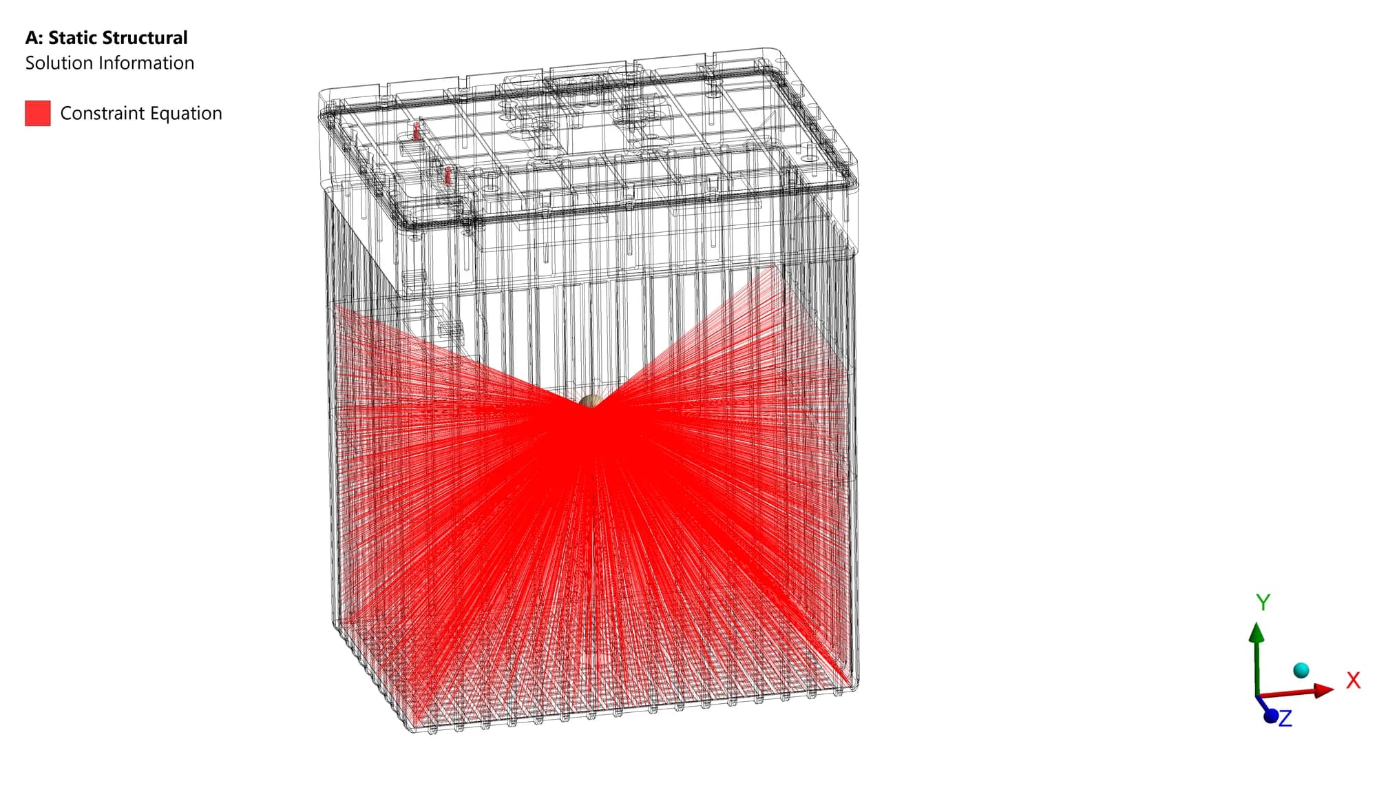
Mass representation and model connections
We represented the 11.5 kg cell-pack mass in the model. This allowed the analysis to account for the internal mass while evaluating the supporting structure
DEFORMATION AND EQUIVALENT STRESS
The response across four analysis cases
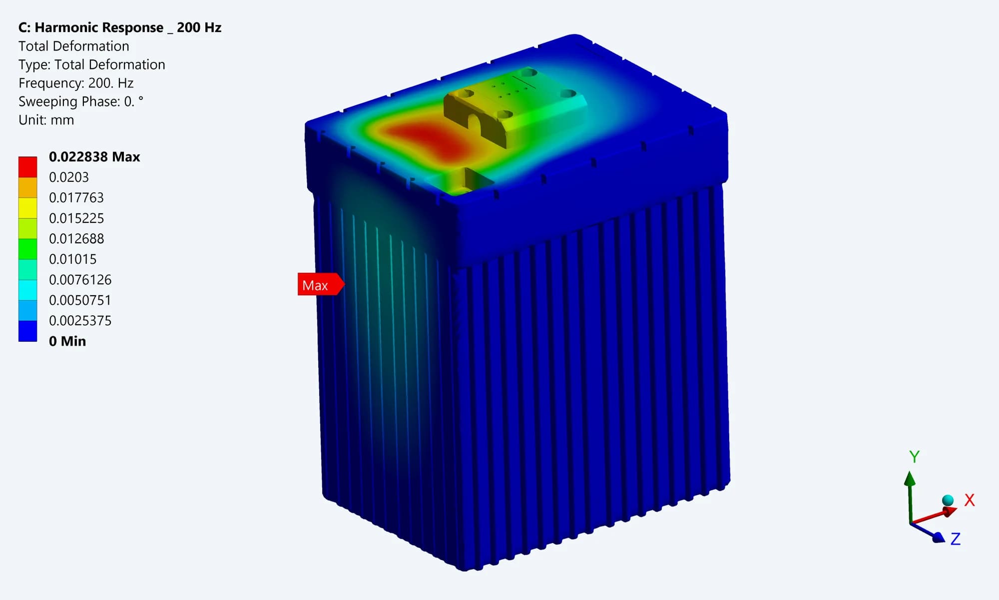
Harmonic response in Y
Total deformation at 200 Hz
0.023 mm deformation
2.8 MPa maximum stress
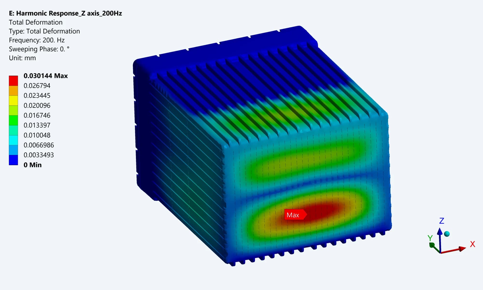
Harmonic response in Z
Total deformation at 200 Hz
0.03 mm deformation
1.34 MPa maximum stress
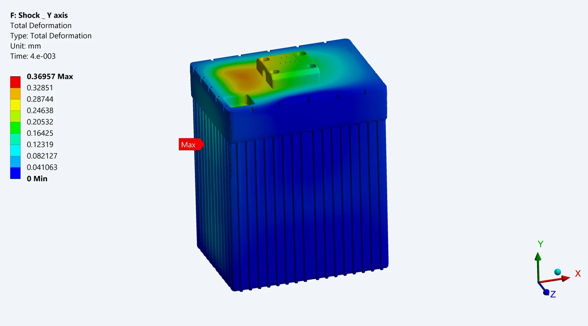
Shock response in Y
Total deformation under the reported shock case
0.37 mm deformation
33.7 MPa maximum stress
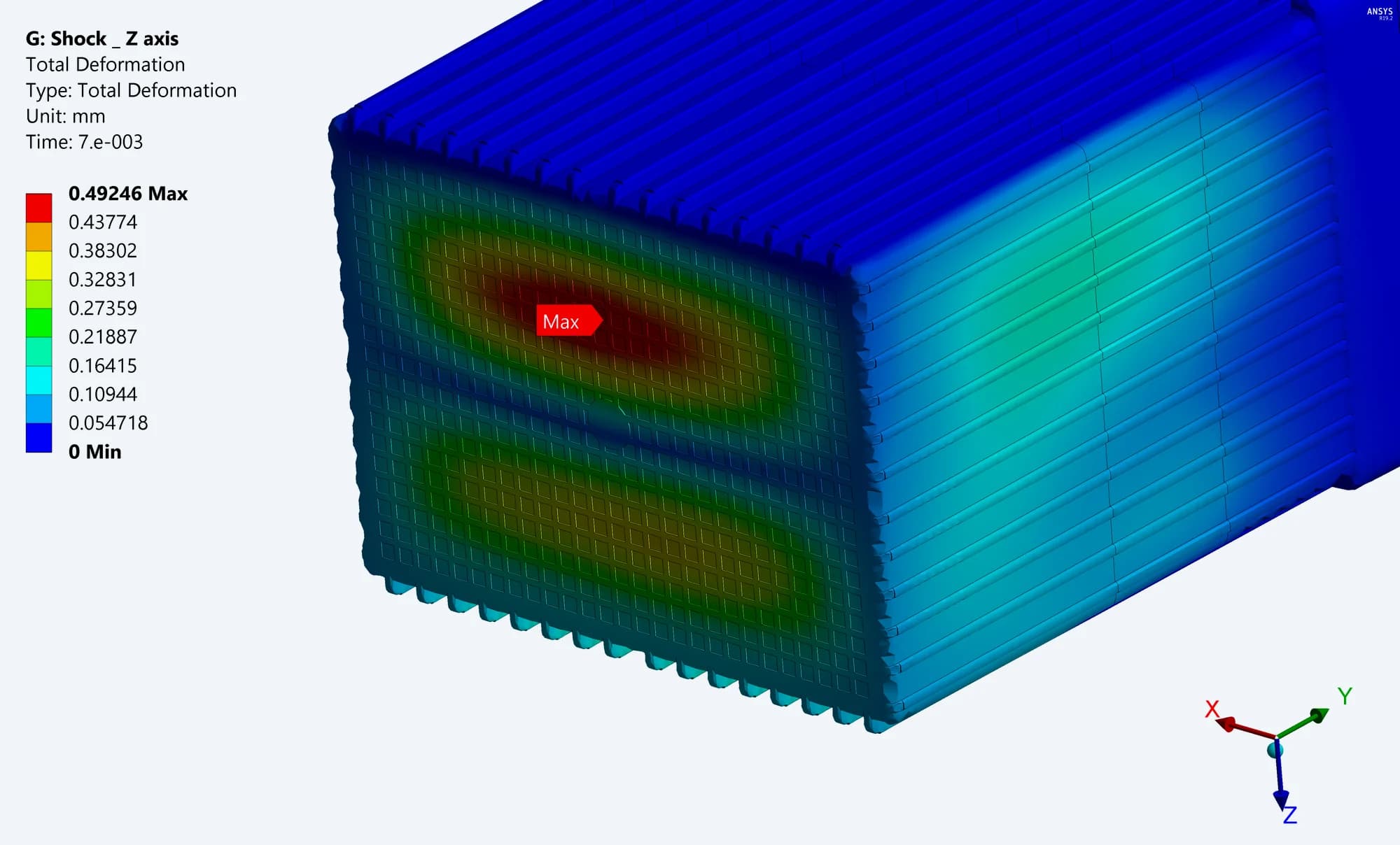
Shock response in Z
Total deformation under the reported shock case
0.5 mm deformation
33.8 MPa maximum stress
CRITICAL COMPONENTS
Stress in the mounts and enclosure parts
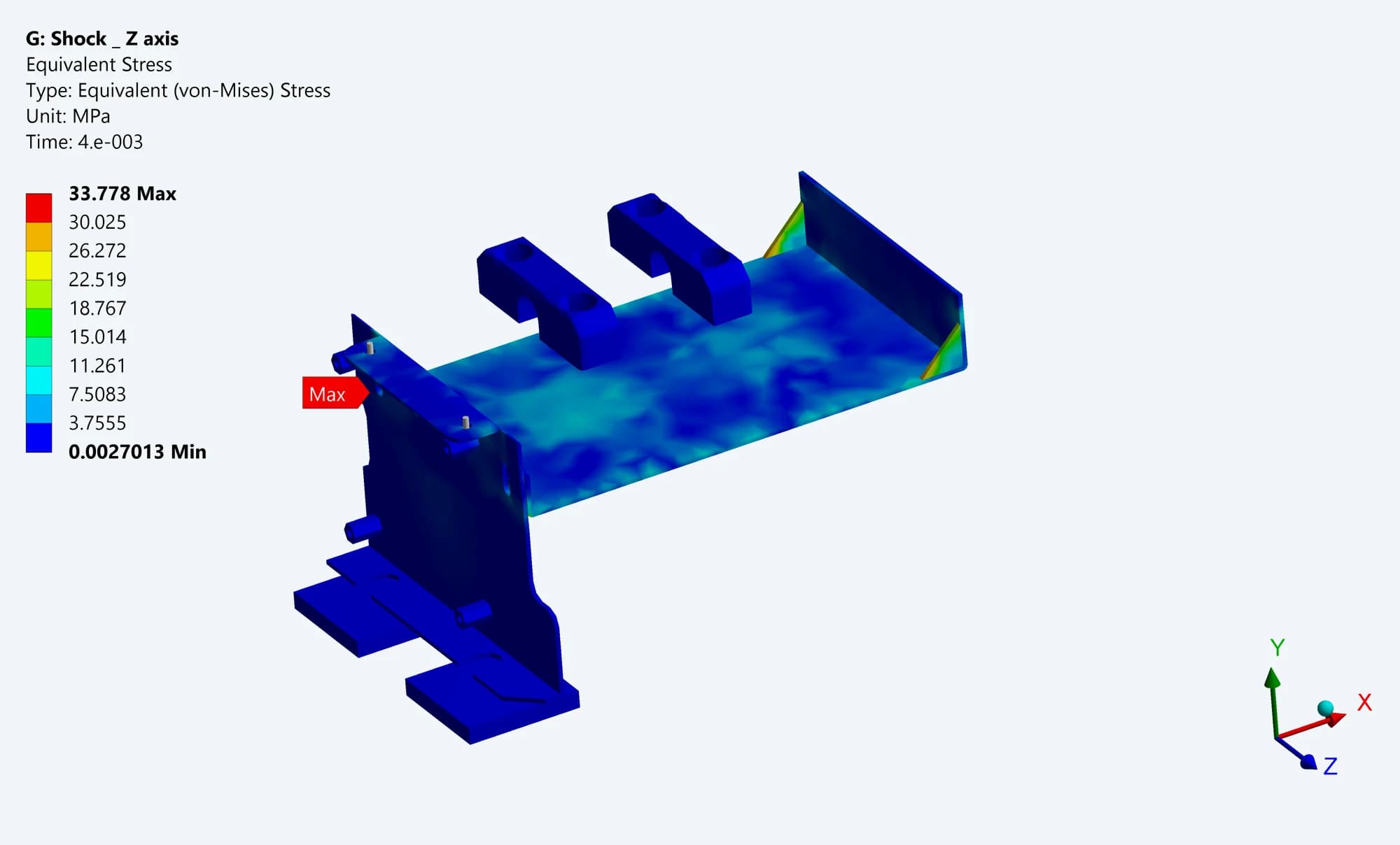
Mounting plates
33.8 MPa
Z-axis shock. The mounting plate assembly carries the peak reported stress
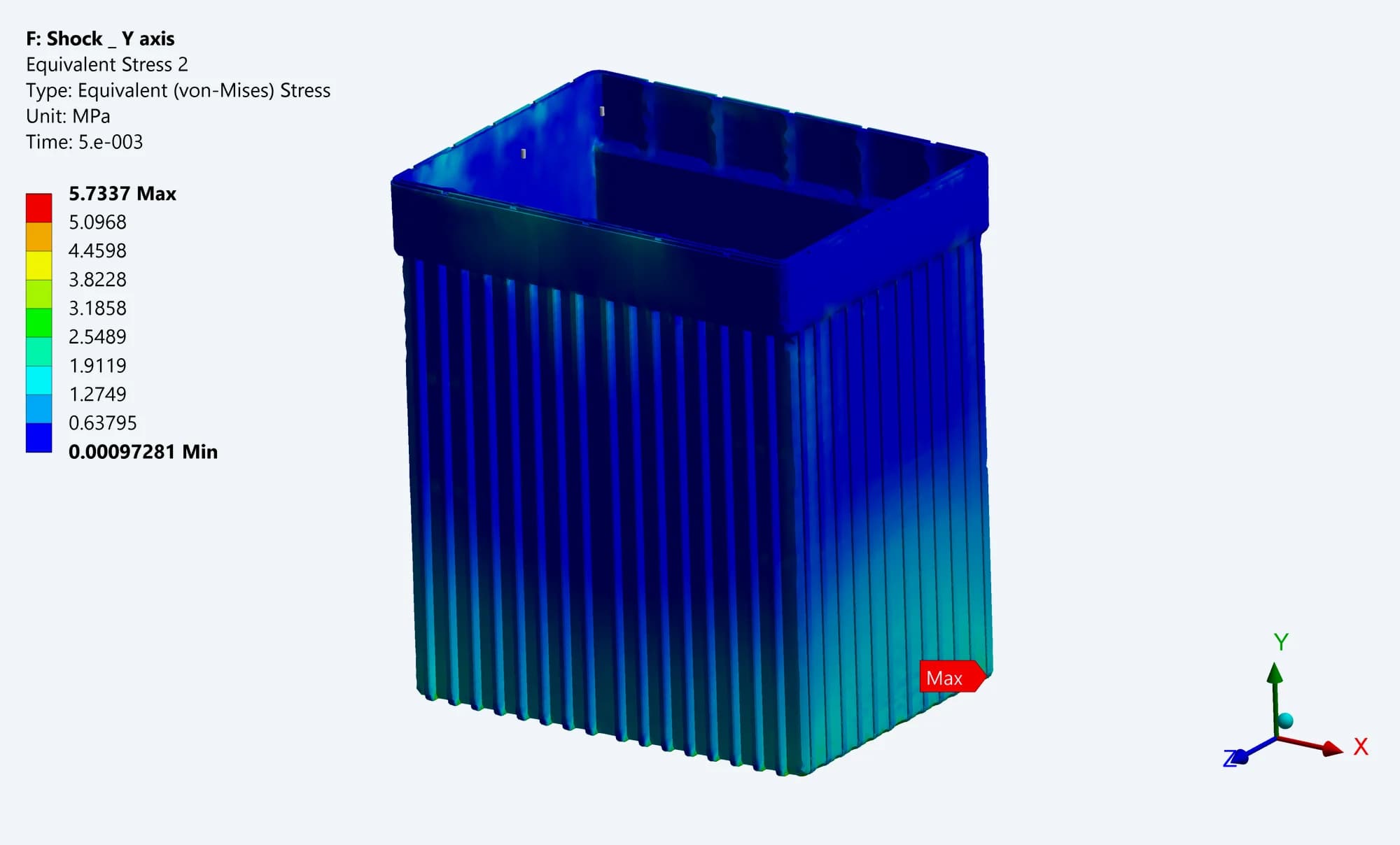
Enclosure / bottom cover
5.7 MPa
Y-axis shock. A separate contour identifies stress in the bottom cover
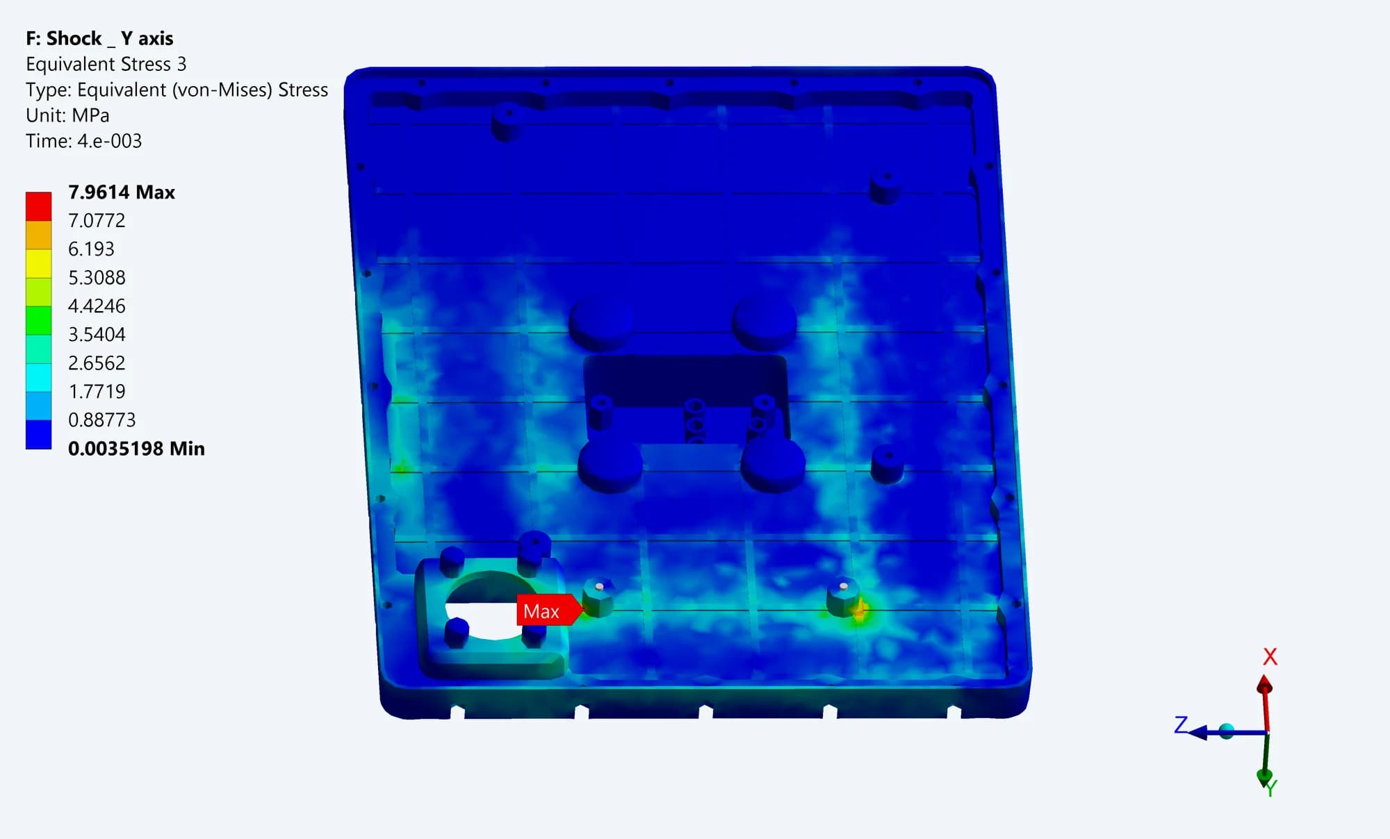
Lid
7.8 MPa
Y-axis shock. The lid review highlights local stress around its features
A documented structural assessment
The reports state that no resonance occurred across 7–200 Hz in Y and Z. For the modelled shock cases, they report stresses below the material yield values and no plastic deformation. Component plots identify the mounting plates as the peak-stress location