
Solar Module Mounting Structure
We developed a manually adjustable mounting structure for a 15-module solar pumping system, combining mechanical design, fabrication detailing, a physical mock-up and structural assessment
Mahindra Susten / PDD
Solar Module Mounting Structure
- Requirement
An adjustable solar array
Support 15 photovoltaic modules for a solar pumping application, with manual rotation and tilt adjustment built into a structure that can be fabricated and assembled on site
- Challenge
Movement and structural support
Carry the module load through bolted purlins, rafters and bracing into a single post, while accommodating the rotating bearing, adjustable connections and wind loading
- Deliverables
Design through to mock-up
Product CAD, detailed assembly drawings, bills of materials and installation records, supported by CFD wind-load evaluation and structural FEA
01 / Design Intent
A central support for an adjustable array
The design brings the array, tracking mechanism and foundation connection into one assembly. Formed purlins support the modules. Rafters and bracing transfer their loads to the horizontal support and vertical post, while the bearing assembly allows the structure to rotate
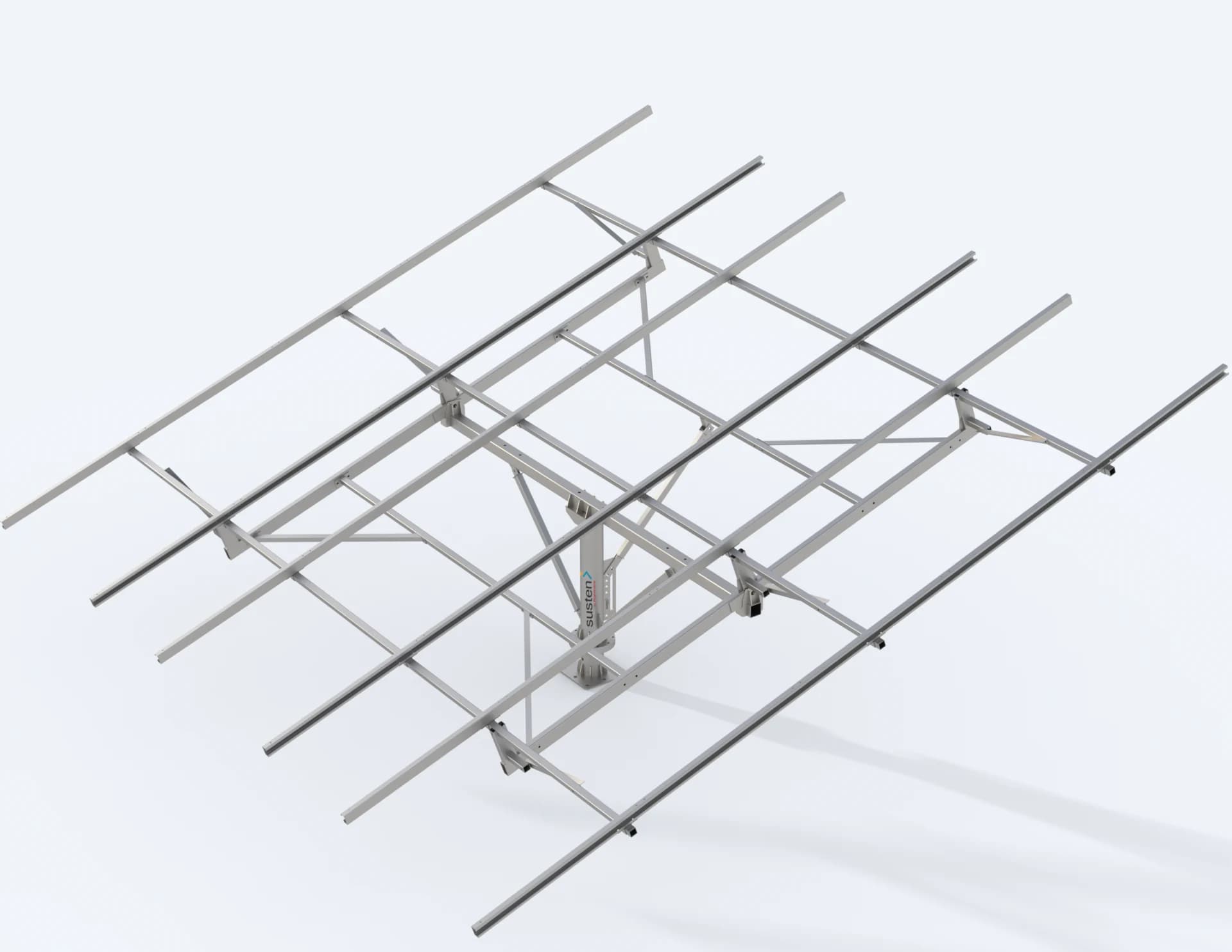
The Product Envelope
5,875 × 5,000 mm
Overall length and width with modules, as recorded in the product and mock-up presentations
232 kg
Reported mock-up structure mass including hot-dip galvanizing
02 / Assembly Development
Building the structure in defined subassemblies
The CAD sequence separates the post and bearing, primary members, secondary supports, rafters and purlins. This makes the interfaces visible before fabrication and establishes the order in which the complete mounting system comes together
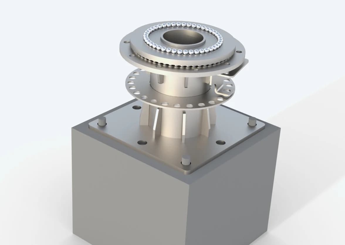
Base and bearing
The base plate, stiffeners, rotational stopper and bearing flanges establish the support and rotation interface
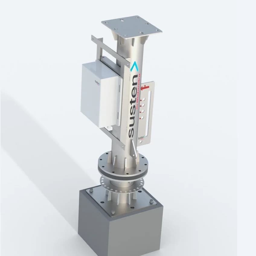
Upper post and brackets
The upper post carries the tilt adjustment plate, top flange and the mechanical mounting frame for the controller
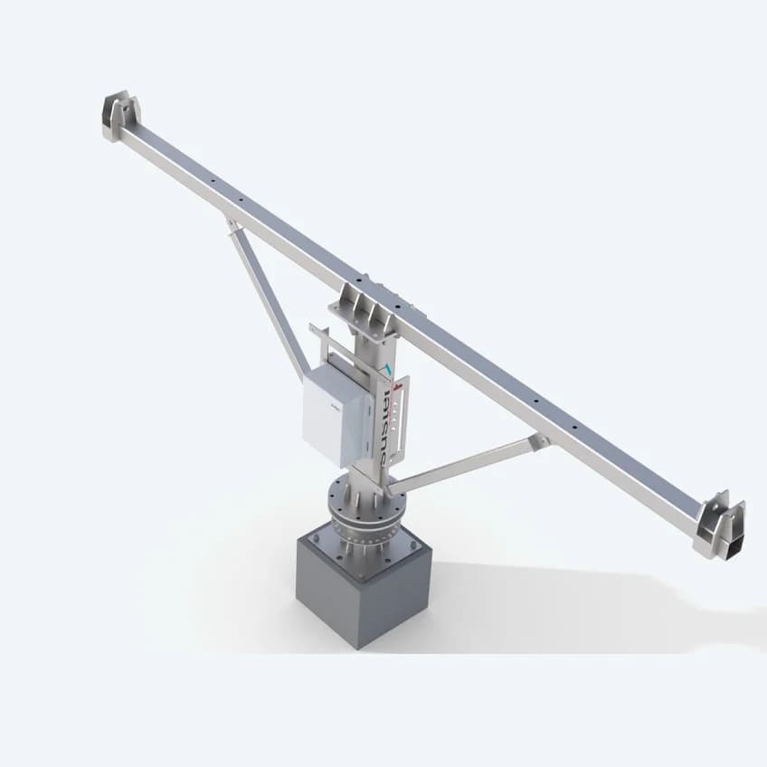
Primary support members
The horizontal beam, hinge plates and bracing connect the post to the array support structure
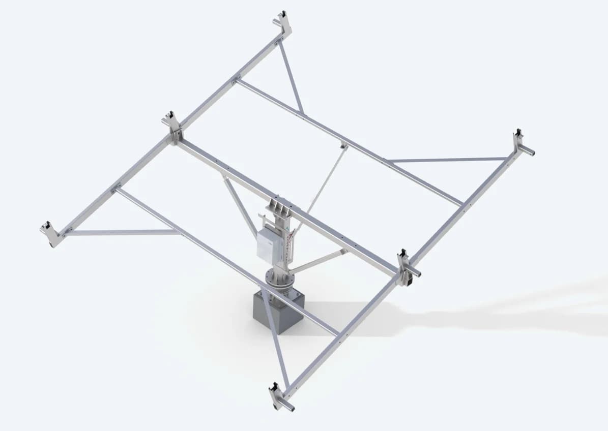
Secondary support members
RHS members and angle-adjustment bracing extend the load path across the array
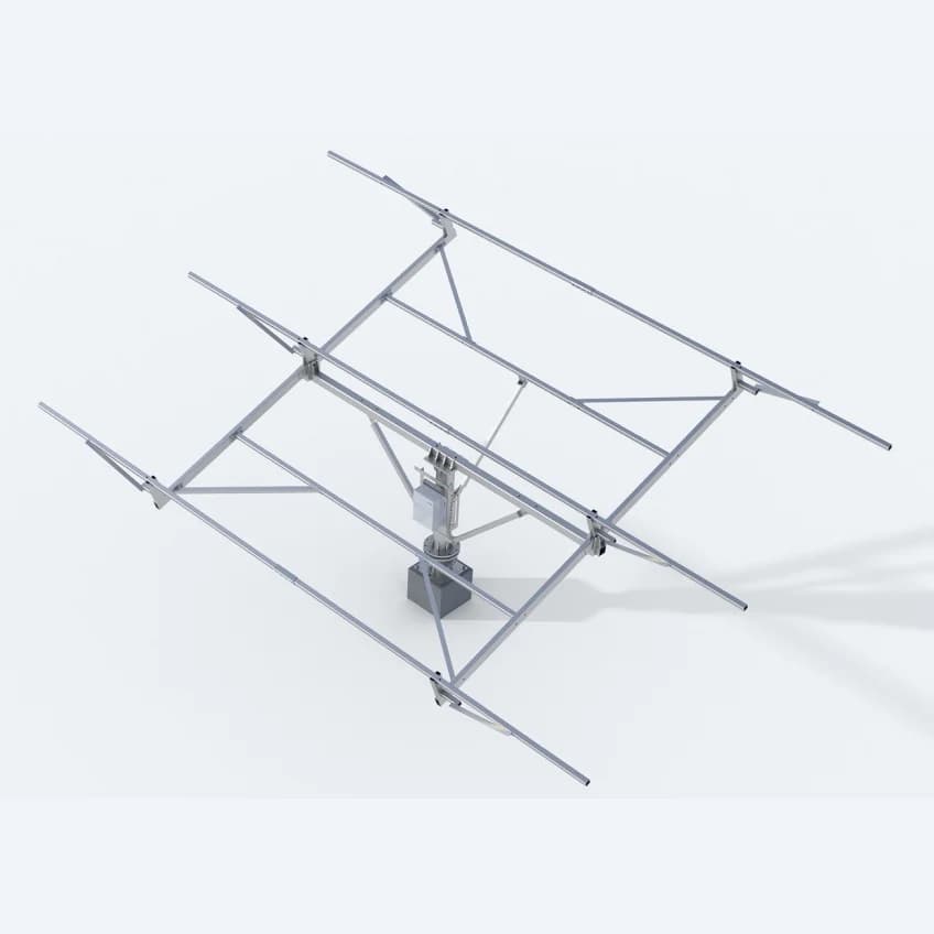
Rafters and overhang support
The rafter arrangement supports the span beyond the central frame and provides attachment points for the purlins
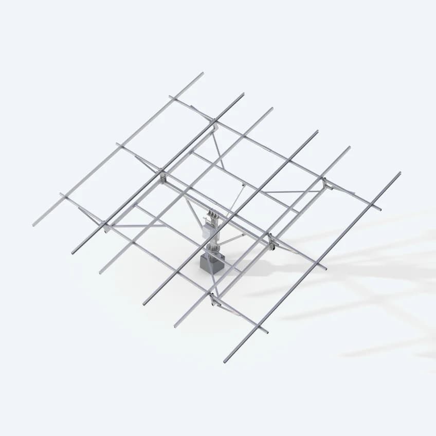
Formed C-purlins
The completed upper grid provides the fixing lines for the modules and distributes their loads into the rafters
03 / Manual Adjustment
Rotation and tilt integrated into the support
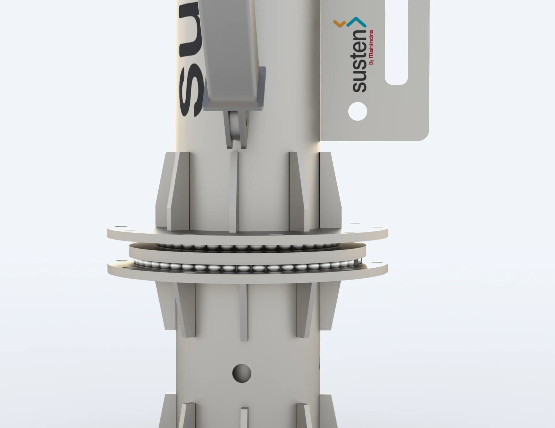
Rotating head and ball races
The bearing assembly carries the upper structure while allowing manual rotation for daily tracking. Flanges, stiffeners and a stopper form part of the detailed arrangement
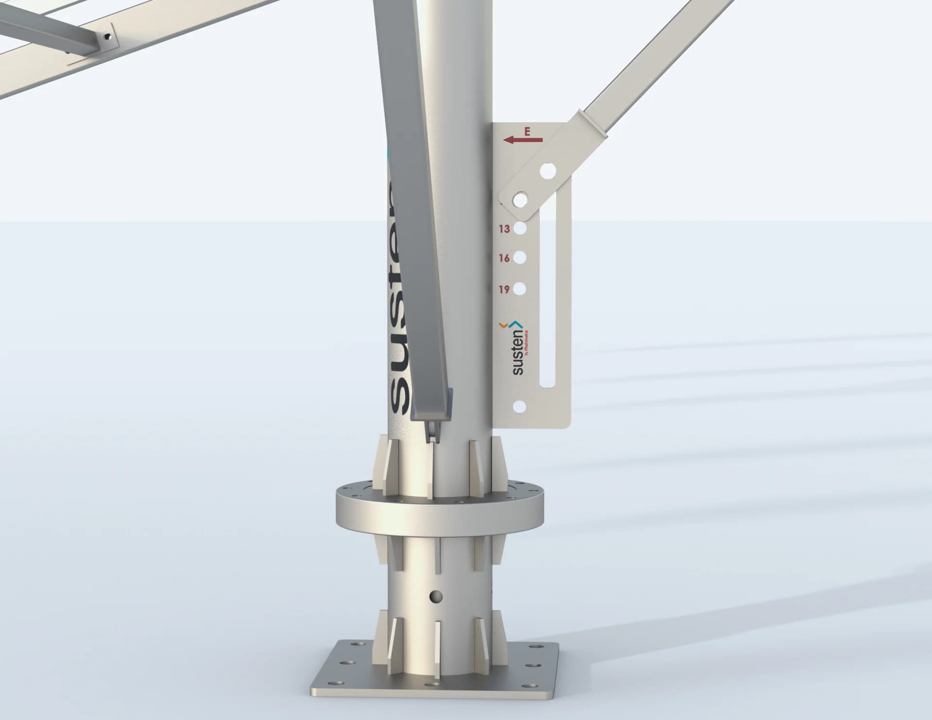
Angle plate and adjustable bracing
The angular plate and bracing define the inclination setting. The connection geometry supports adjustment while maintaining a load path back to the central post
04 / Geometry & Clearances
Checking the operating envelope
General arrangement views describe the array in front and side elevation. The project presentation records a horizontal height of 1,532 mm, with near and far edge heights of 604 mm and 2,232 mm in the illustrated inclined position
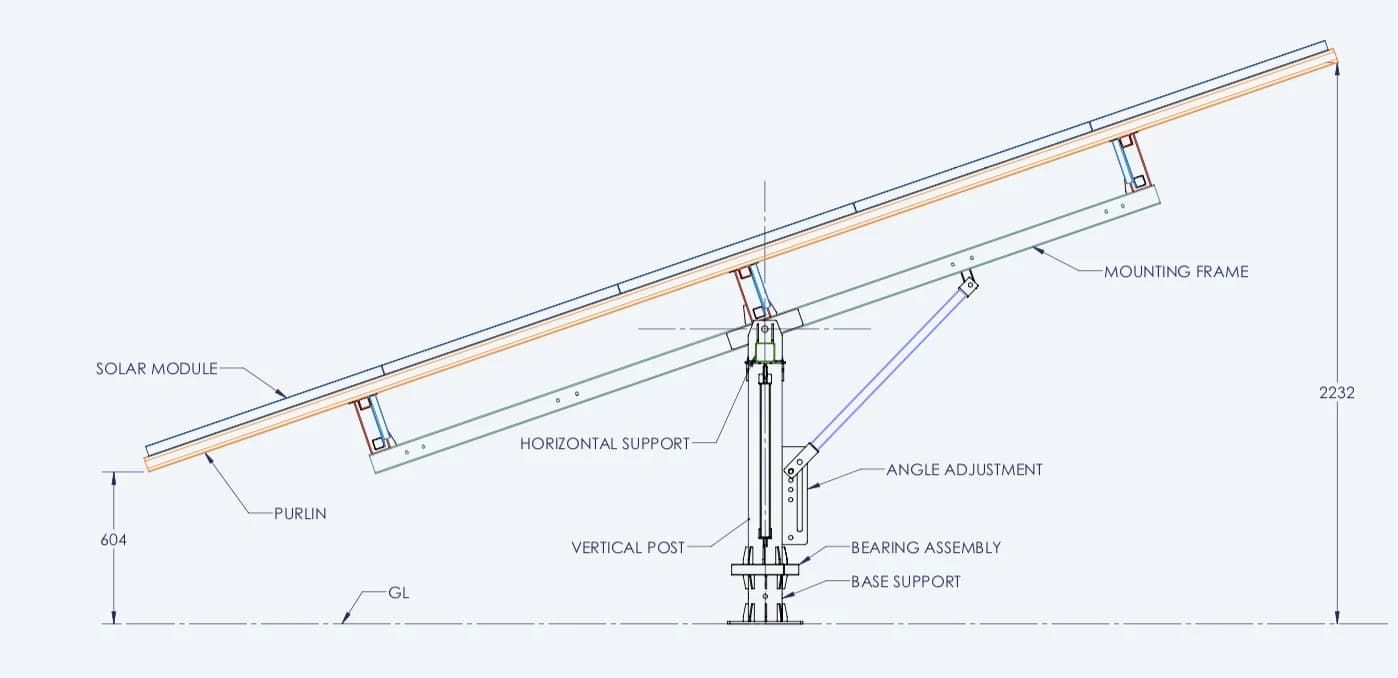
Inclined side elevation
The side view relates panel inclination, ground clearance and the position of the adjustment members
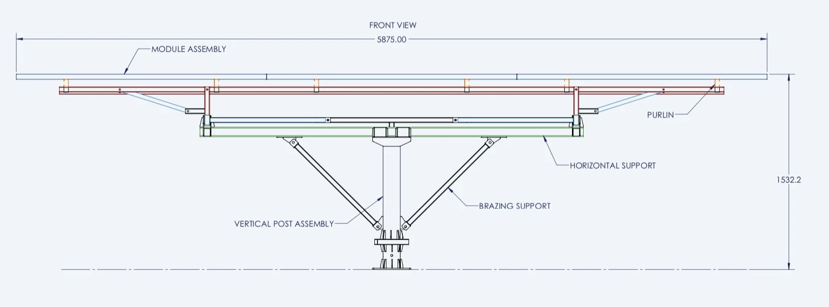
Front elevation
The front view establishes the span, symmetry and connection of the upper support frame to the central post
05 / Design for Fabrication
Assembly details that support manufacture
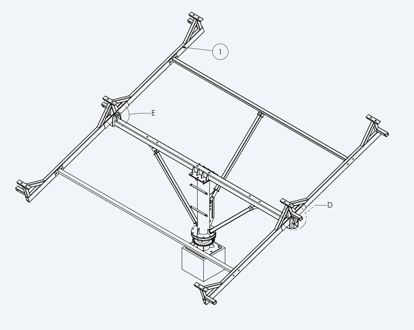
H-frame and connection detail
The fabrication package defines the frame subassemblies, clevis interfaces and connection arrangement. This excerpt focuses on the geometry
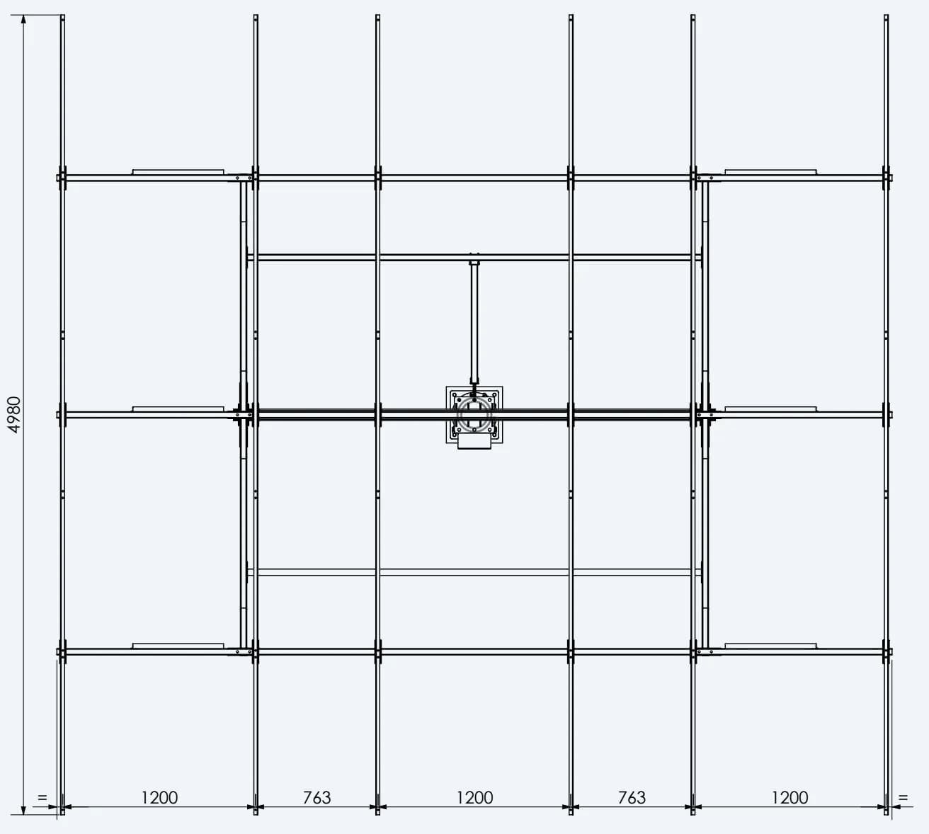
Purlin positions and fixings
Plan and detail views establish purlin spacing and the fixing relationship to the supporting tubes. The archive also contains flat-pattern DXF files and parts lists
The mock-up record lists cutting, grinding, drilling, MIG welding, laser cutting and purlin roll forming. Drawing revisions, fastener schedules and packing checklists supported the work between component manufacture and site assembly
06 / Foundation & Site Preparation
Preparing the anchor interface
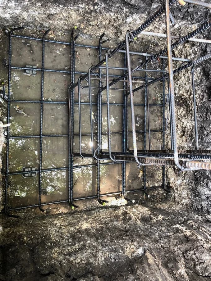
Reinforcement preparation
The photographed reinforcement cage establishes the site preparation stage before the pedestal is cast
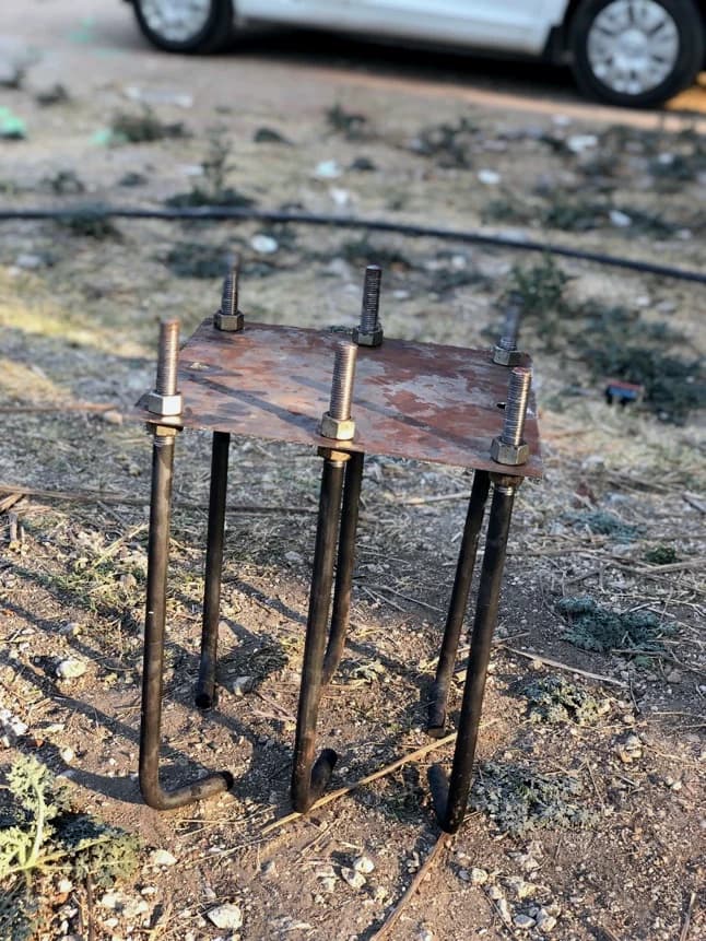
Anchor-bolt positioning
The J-bolt cage locates the fasteners that will receive the vertical-post base plate
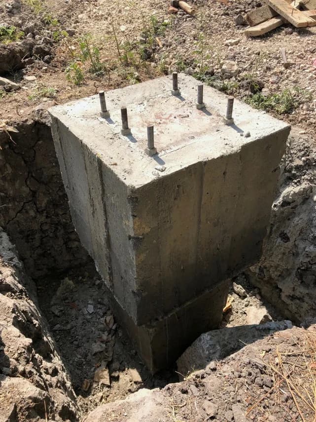
Completed pedestal
The exposed anchors provide the mounting interface for installing and securing the structure
07 / Physical Mock-up
Assembling and reviewing the complete structure
Installed side view
The mock-up shows the complete array, its inclination and the central foundation in the actual site setting
Underside and support layout
The rear view makes the purlin fixings, rafters and central bracing visible beneath the modules
- Recorded fabrication duration
- 4 days
- 2 welders and 2 helpers
- Recorded installation duration
- 2 h 30 min
- 2 technicians and 1 helper
- Fasteners recorded
- 263
- Installation included module fixing
08 / Finite Element Model
Tracing loads through the frame and connections
The structural model represents the upper frame, post, bearing region, brackets and bolted interfaces. The analysis reviews the assembly response together with local behaviour at the connections, where concentrated stress can develop
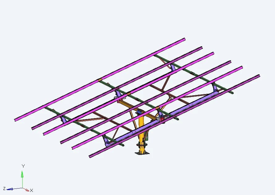
Geometry prepared for analysis
The structural arrangement is reviewed without the panel surfaces so the supporting members and connections can be represented explicitly
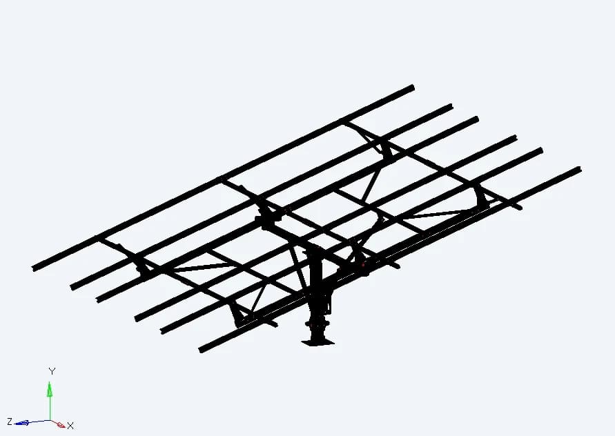
Meshed assembly
The discretised model provides the basis for calculating deformation and stress under the defined dead-load and wind-load cases
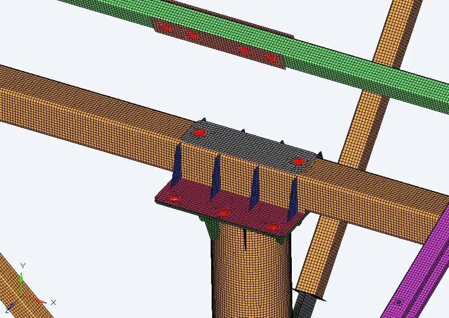
Head and horizontal support
The model resolves the central connection between the horizontal member and the upper post
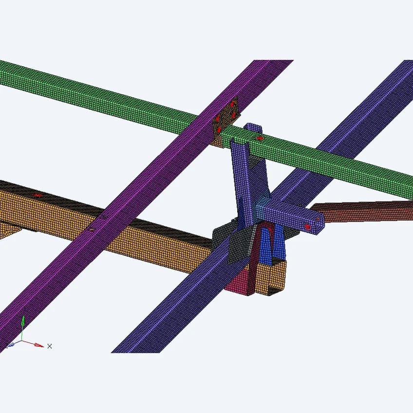
Bracing and cleat connections
Bracing interfaces are represented so local connection response can be inspected alongside global frame behaviour
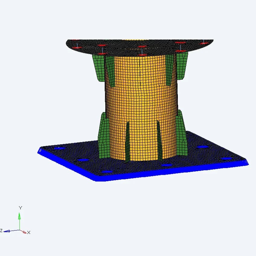
Base restraint
The base restraint represents the foundation connection used by the model. This assumption governs the load path and resulting displacement
Loading basis used for the mock-up analysis
| LOAD CASE | MODEL INPUTS | ASSESSMENT |
|---|---|---|
| Dead load | 219 kg structure + 15 panels at 25 kg each | Self-weight and module payload |
| Dead load + wind | Same structural and panel loads, with panel wind pressures | Frame and connection response to wind |
The 219 kg analysis mass and 232 kg galvanized mock-up mass are recorded on different bases. The wind study targets an equivalent wind speed of 150 km/h
09 / Wind-load Development
CFD to evaluate the pressure over the array
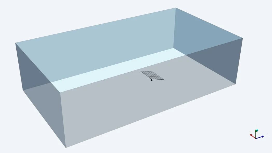
Virtual wind-tunnel domain
The array is placed in a surrounding air volume to study the flow around the inclined panels
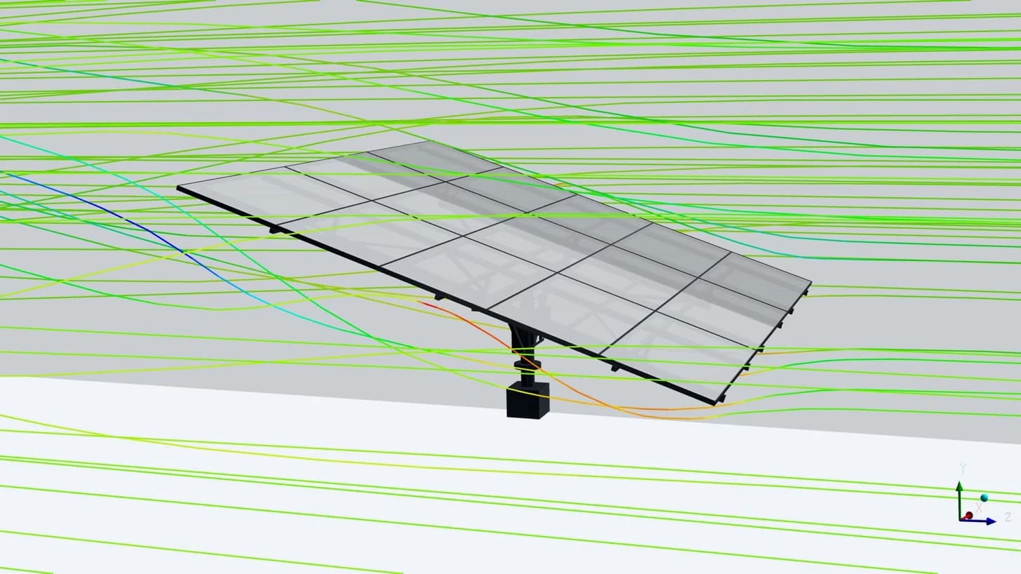
Flow around the modules
Pathlines illustrate how the approaching flow passes over and around the array, providing context for the panel pressure distribution
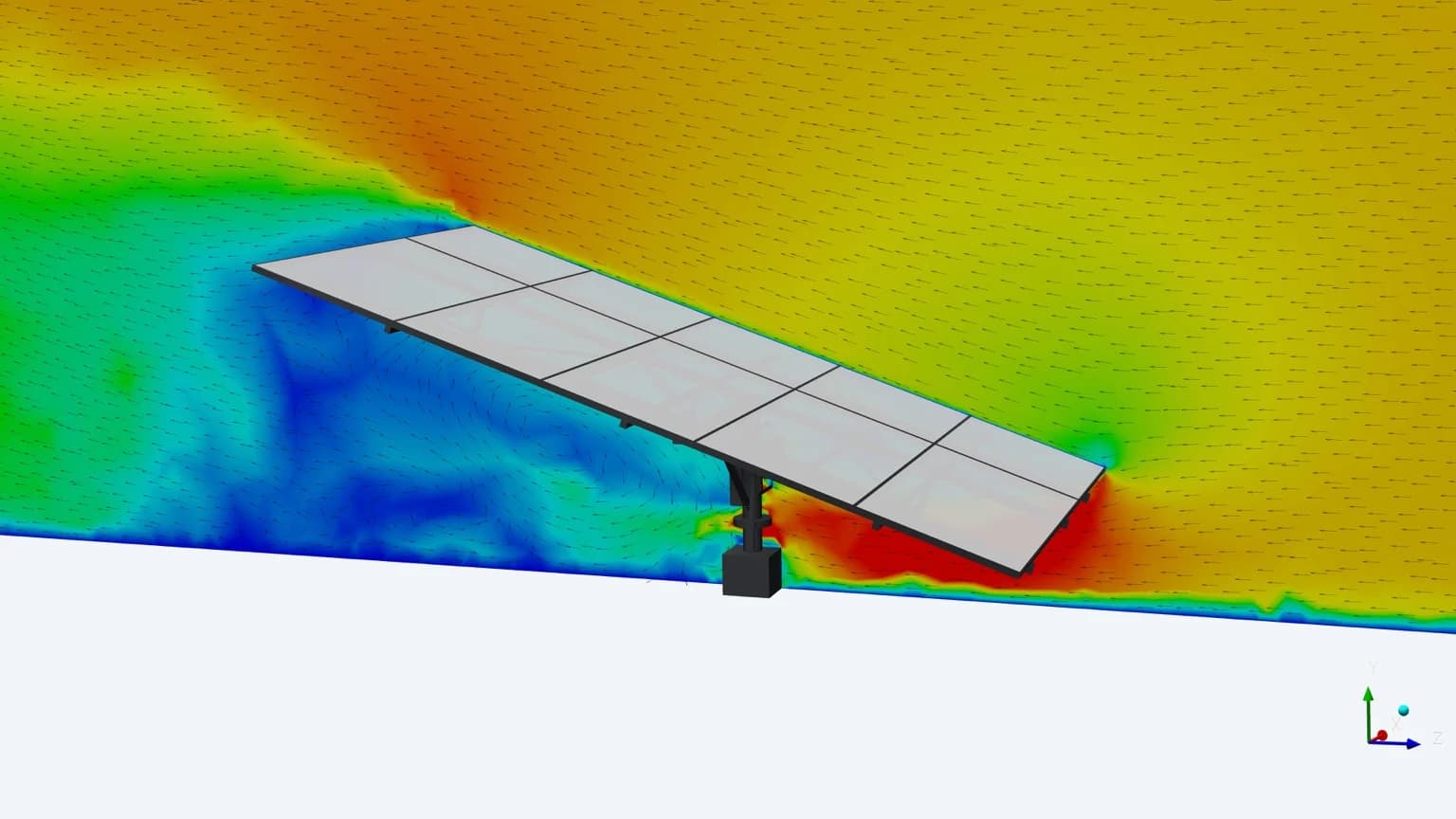
Non-uniform panel loading
The velocity view shows the disturbed flow beneath and behind the array. The project presentation reports individual panel pressures between 208 Pa and 593 Pa for this wind setup These panel loads provide the input for the wind-load structural assessment
10 / FEA: Dead Load
Deformation and stress under the module weight
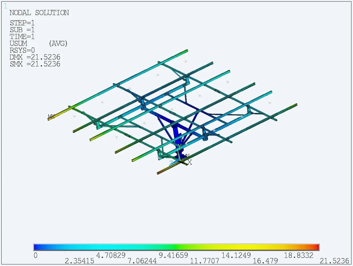
21.5 mm maximum deformation
The dead-load result places the largest displacement at the free purlin edges. The contour shows how the central support and overhanging members respond together
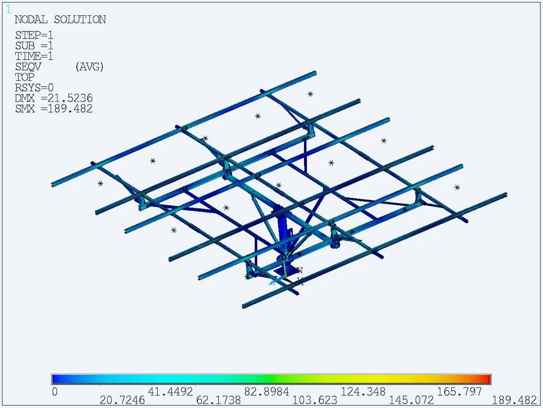
189 MPa reported maximum stress
The assembly stress result directs attention to the post and its bracing connection. Component plots then examine the individual members and local interfaces
11 / FEA: Wind Load
Reviewing global movement and local peaks
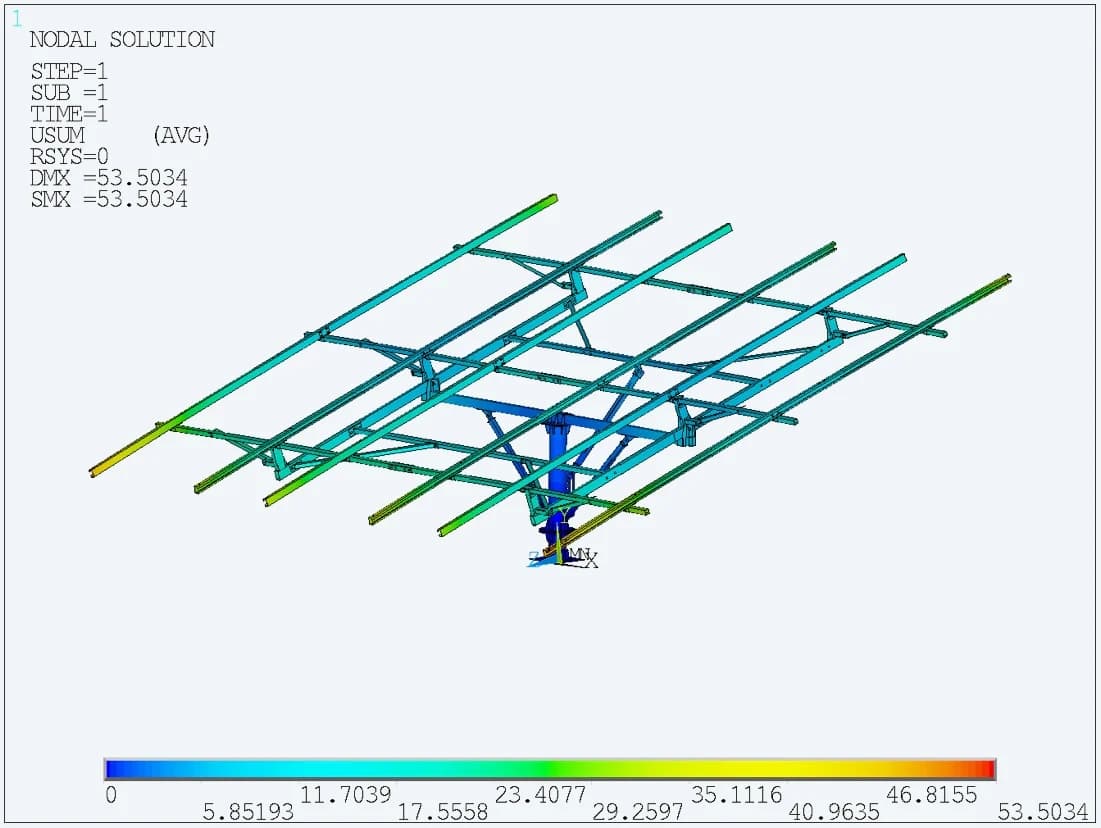
Displacement under wind loading
The contour places the largest movement at the purlin edges. The displayed maximum is approximately 53.5 mm for this model and load case
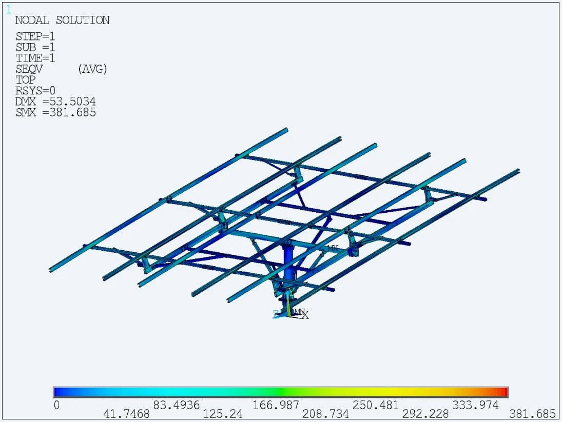
Localized assembly stress
The wind-load stress plot reports a local maximum of approximately 382 MPa. The analysis follows this with component plots to identify where the response is concentrated
The deformation value above follows the contour legend. Its source slide caption states 16.4 mm, while the report summary states 53 mm. Local peaks are retained here and are not treated as proof of structural acceptance
12 / Component-level Review
The post and rafter connection regions
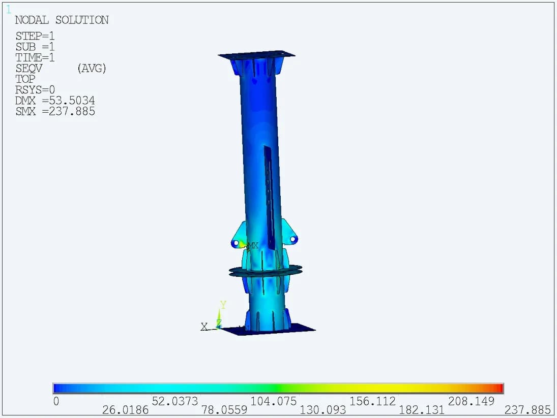
Vertical post and bracing interface
The component result reports approximately 238 MPa near the bracing plate connection, identifying an interface for detailed review
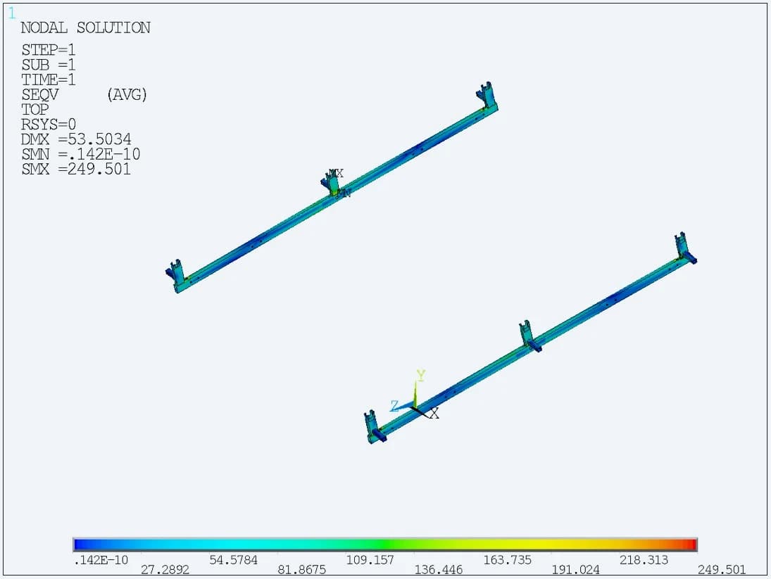
Rafter / RHS assembly
The component result reports approximately 250 MPa. Comparing individual members makes the design review more specific than relying on a single assembly peak
The work combined the overall deformation pattern with stresses in the post, horizontal support, rafters, purlins and their connections. This provided a basis for reviewing member sizes, support positions and connection details within the analysed configuration
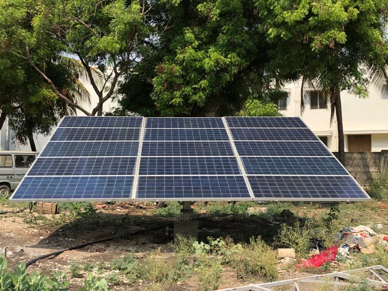
A developed mounting system, assembled and assessed
The project produced a detailed mechanical design and a physical 15-module mock-up. CAD, fabrication drawings and assembly records connected the design intent to the built structure CFD and FEA added a documented view of the wind loads, frame deformation and critical connection stresses