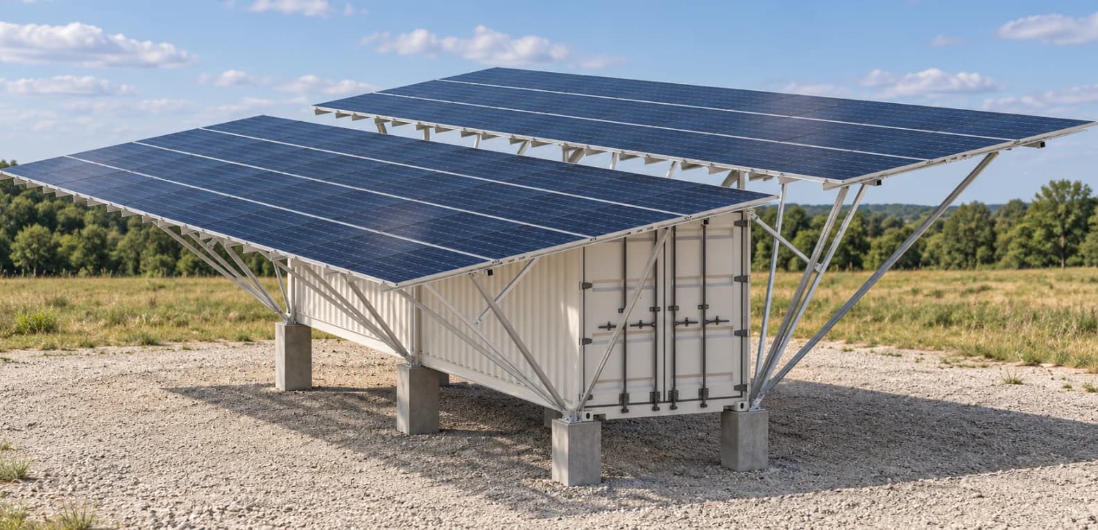
Containerized Energy System
40 ft HMG: product engineering, FEA and CFD
HUSK / Product Development
Containerized Energy System
- Requirement
Bring the systems into one package
Develop a 40 ft container arrangement for battery and inverter equipment, with solar modules above and access for operation and maintenance
- Challenge
Coordinate the interfaces
Resolve the solar-support load path and the internal equipment layout while accommodating heat removal, cable routes and service access
- Deliverables
An engineering development package
Product layouts and renders, structural analysis, ventilation CFD, detailed assembly and part drawings, and bills of materials
- High-cube container platform
- 40 ft
- Solar array in the design basis
- 70 modules
- Documented tilt configurations
- 10° / 25°
Development Programme
The engineering process

Step 01: Configure
Arrange the container, equipment zones and solar array

Step 02: Develop
Resolve the supports, joints and internal assemblies

Step 03: Analyse
Study wind response and ventilation behaviour

Step 04: Detail
Translate assemblies into drawings and parts lists

Step 05: Document
Present the design and the findings for review
01 / Product Architecture
A container platform with an integrated solar canopy
The product combines a high-cube container with a solar module mounting structure. The array extends beyond the container footprint, so its supports and braces form a major part of the product architecture. Raised supports provide the foundation interface shown in the design
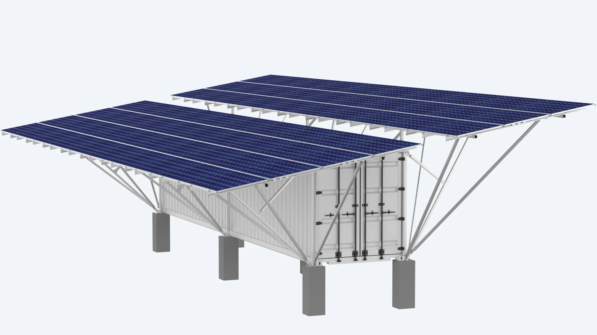
| DESIGN FEATURE | RECORDED ARRANGEMENT |
|---|---|
| Container envelope | 12,192 × 2,438 × 2,896 mm in the general arrangement |
| 10° module layout | 40 modules on one array section and 30 on the other |
| Interior zones | Battery room, inverter room and front / guard room |
| Integration features | Equipment racks, partitions, ducts, cable routing and access |
Design basis: general arrangement dated 12 July 2022. Dimensions describe the container, not the complete canopy footprint.
02 / Configuration Development
Solar-angle and configuration development
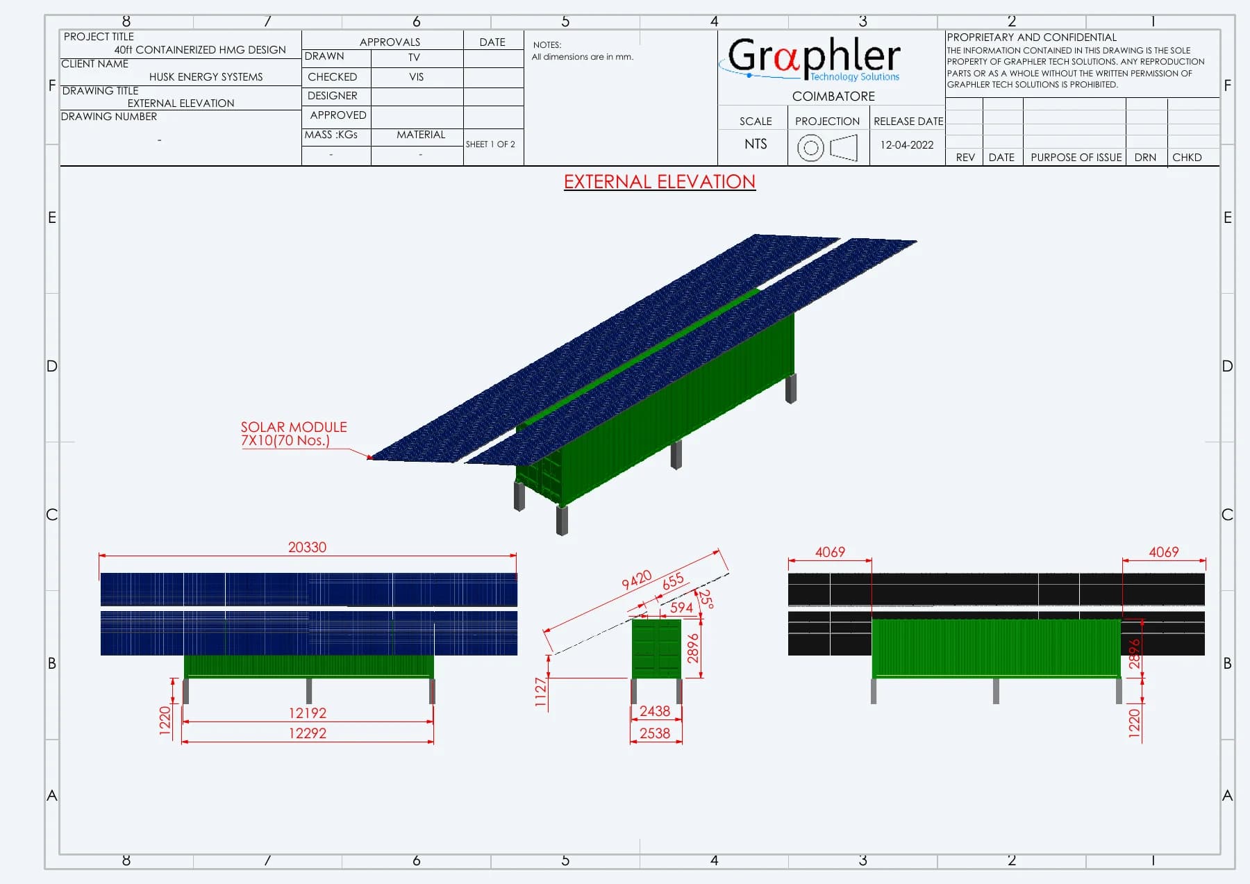
25° concept arrangement
The early concept sheet sets out a 70-module solar plane above the container and establishes the overall envelope and support positions
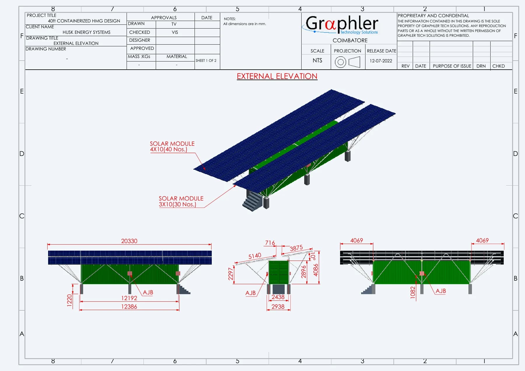
10° general arrangement
The later general arrangement records a split array of 40 and 30 modules and connects the external form to the internal container layout
03 / Structural Development
Canopy supports and container connections
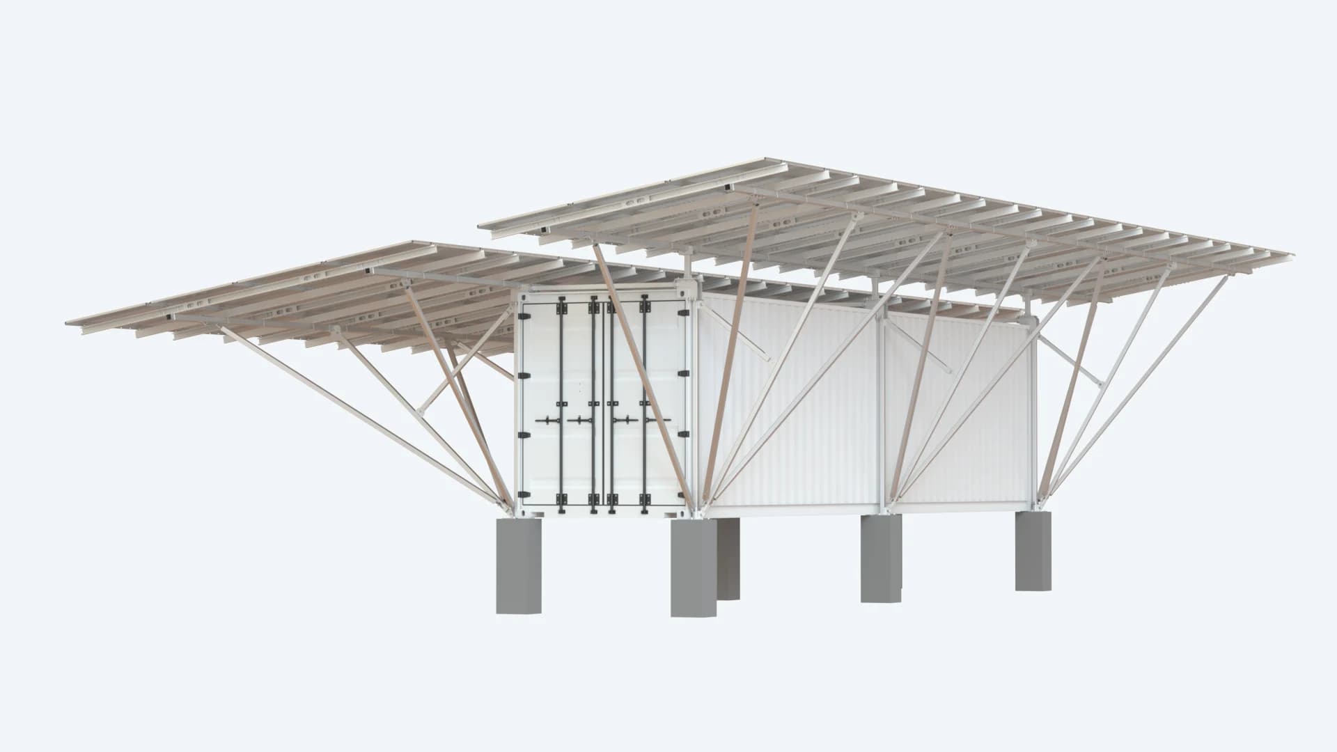
Rafters, purlins and bracing
The underside view exposes the member arrangement beneath the modules. Repeated rafters and purlins support the solar plane, while diagonal members connect the outer edges to the main structure
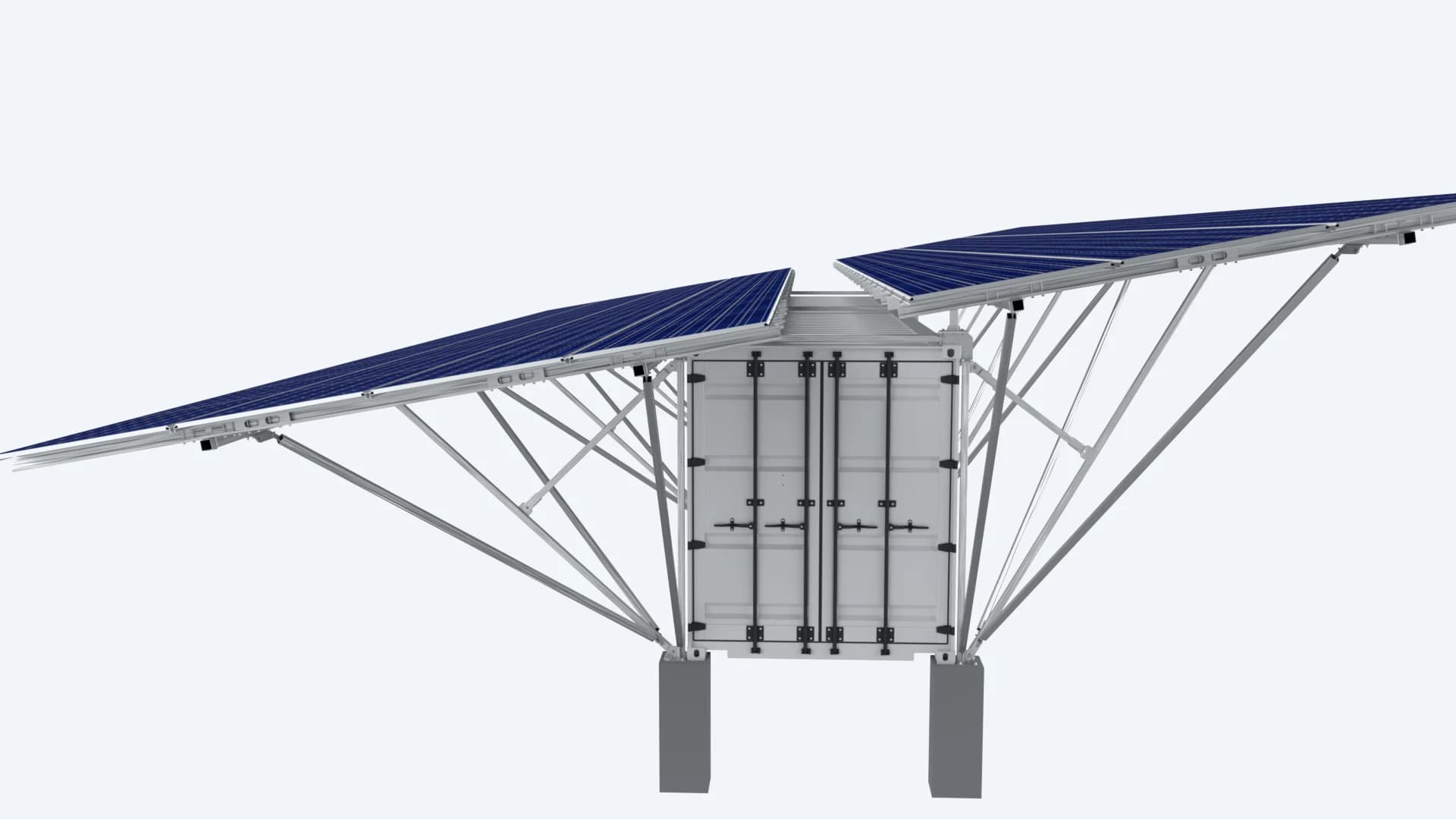
Container and support interfaces
The end view makes the canopy overhang and bracing geometry clear. Pivot blocks, column bases and ISO corner-casting connections appear as specific interfaces in the structural analysis
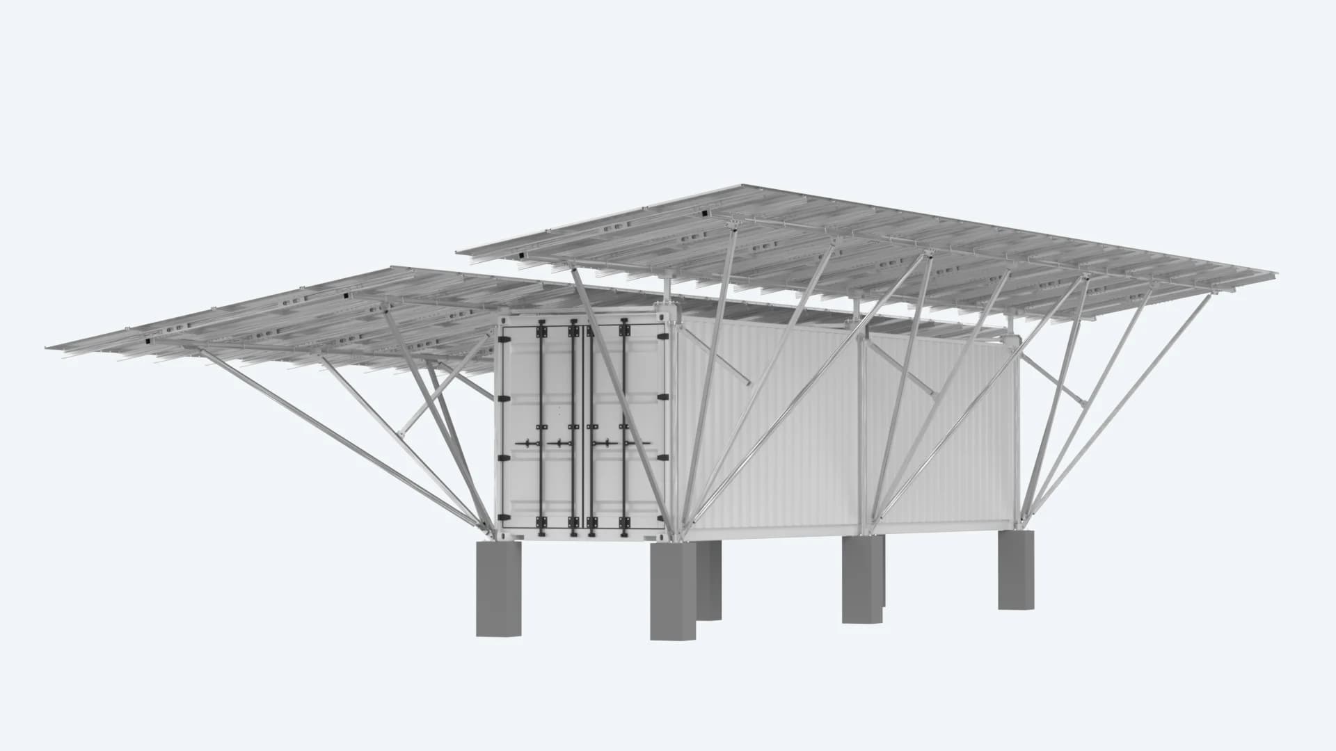
An assembly of defined interfaces
Member geometry, attachment locations and connection details were developed together. The analysis then examined the overall frame and the local regions where forces pass between parts
04 / Internal Packaging
Equipment zoning and service access
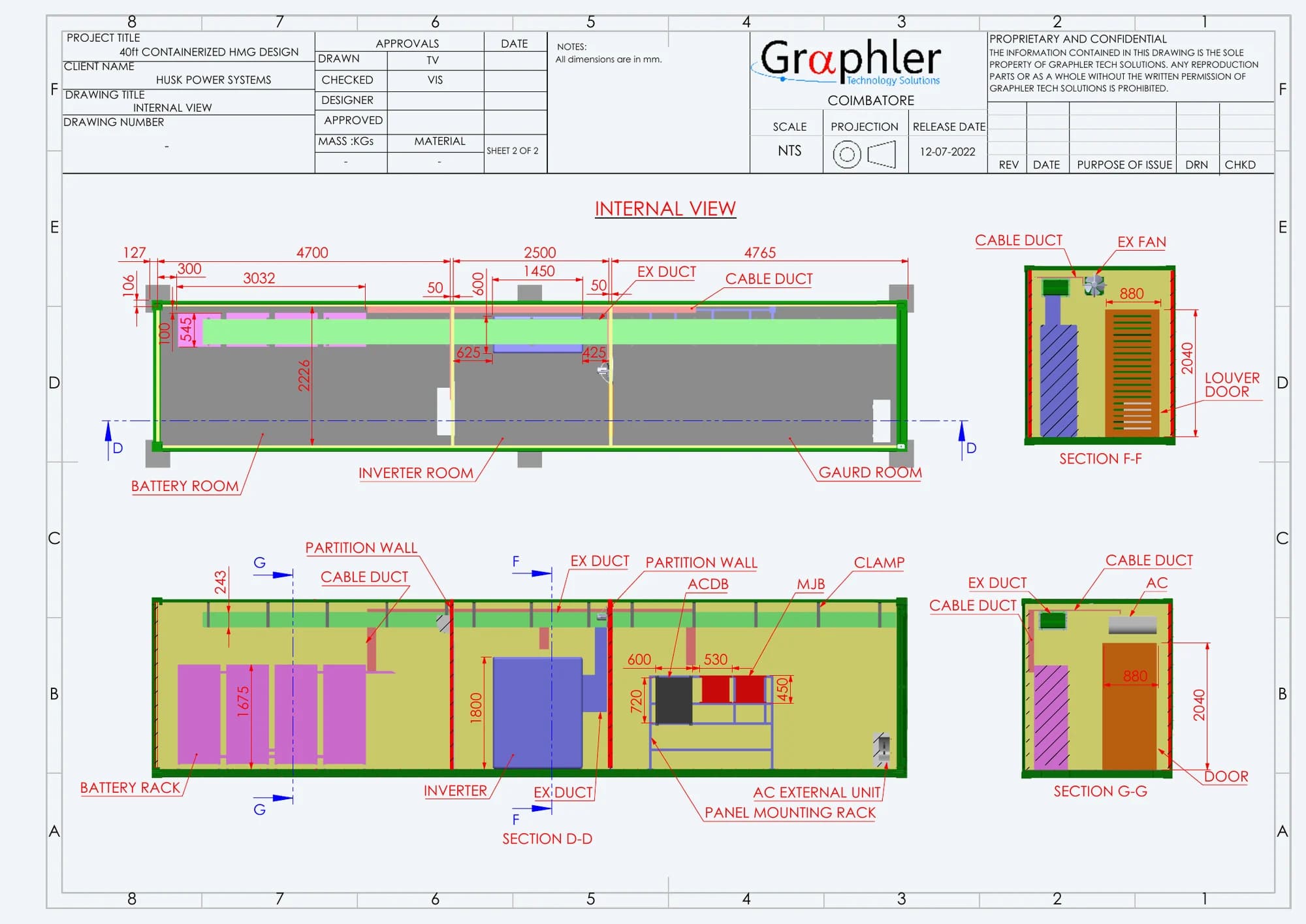
The internal layout separates the battery, inverter and front-room zones. Battery racks and electrical panels occupy defined locations along the container, with partitions and openings shaping both access and airflow. The overhead exhaust duct and cable routes need to coexist with these equipment zones
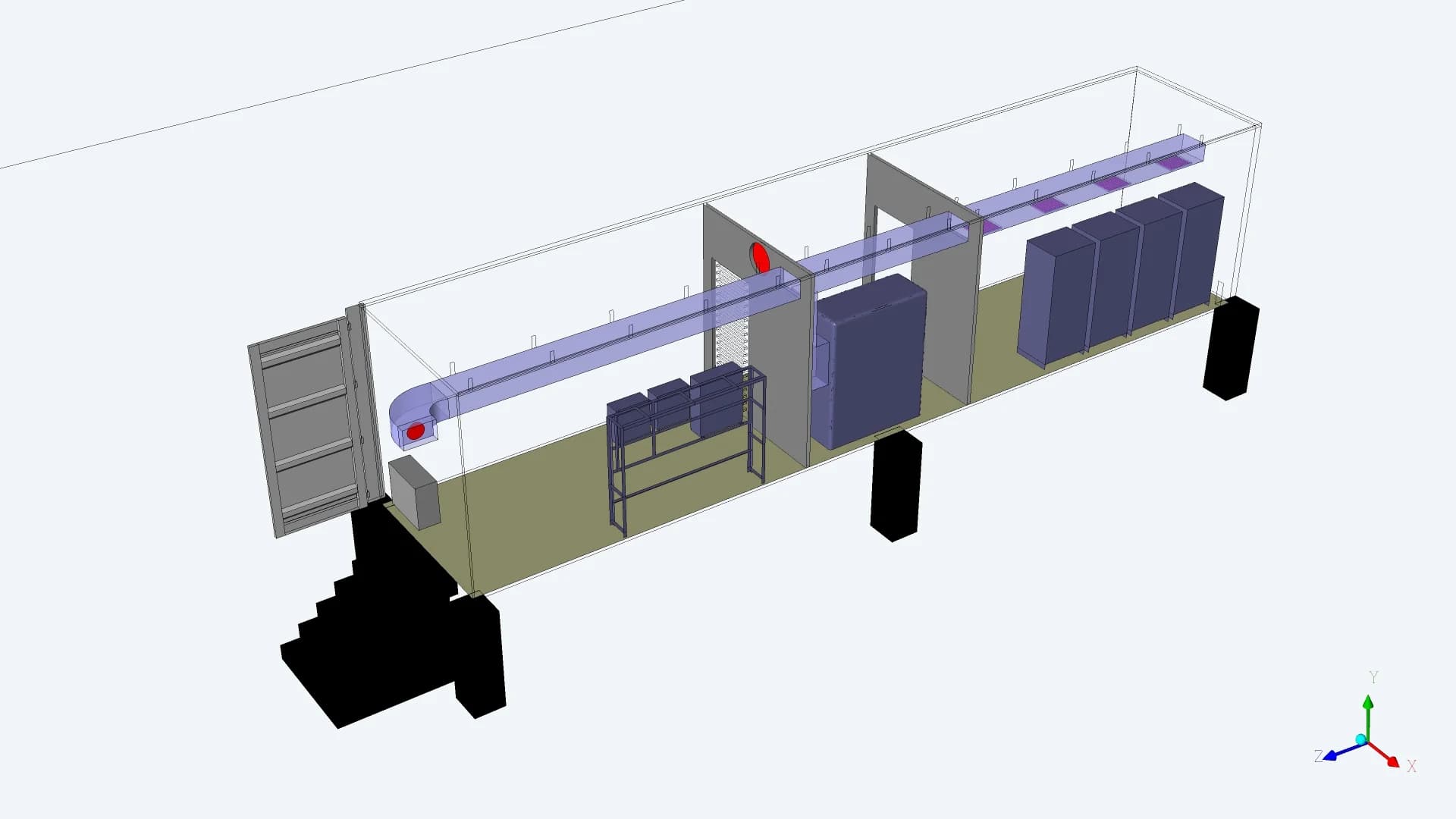
05 / Equipment Integration
Mounting frames, insulation and access assemblies
01 Battery mounting frame
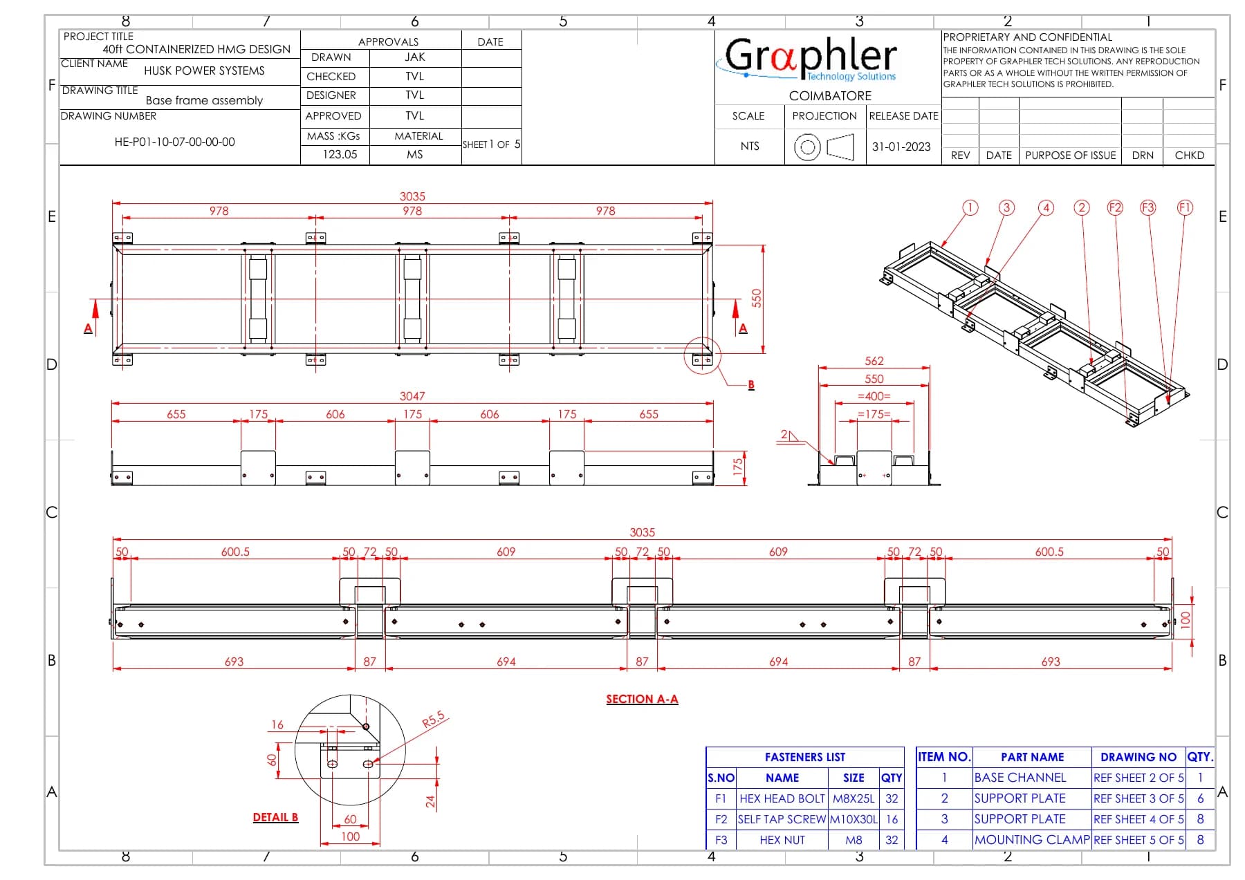
The frame drawing defines the supporting members and plate interfaces beneath the battery equipment, with dimensions and a fastener schedule
02 Panel support rack
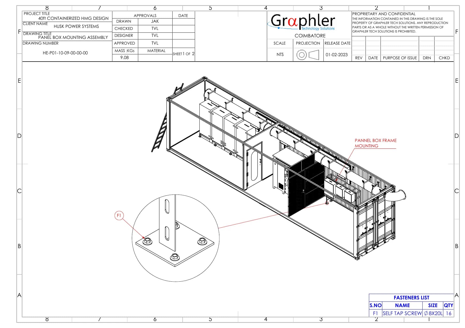
The rack drawing identifies the panel support structure and its mounting details within the container assembly
03 Insulation and compartment definition
The PUF panel assembly describes the insulated enclosure arrangement and the openings that must align with the equipment and duct layout
04 Access to the raised container
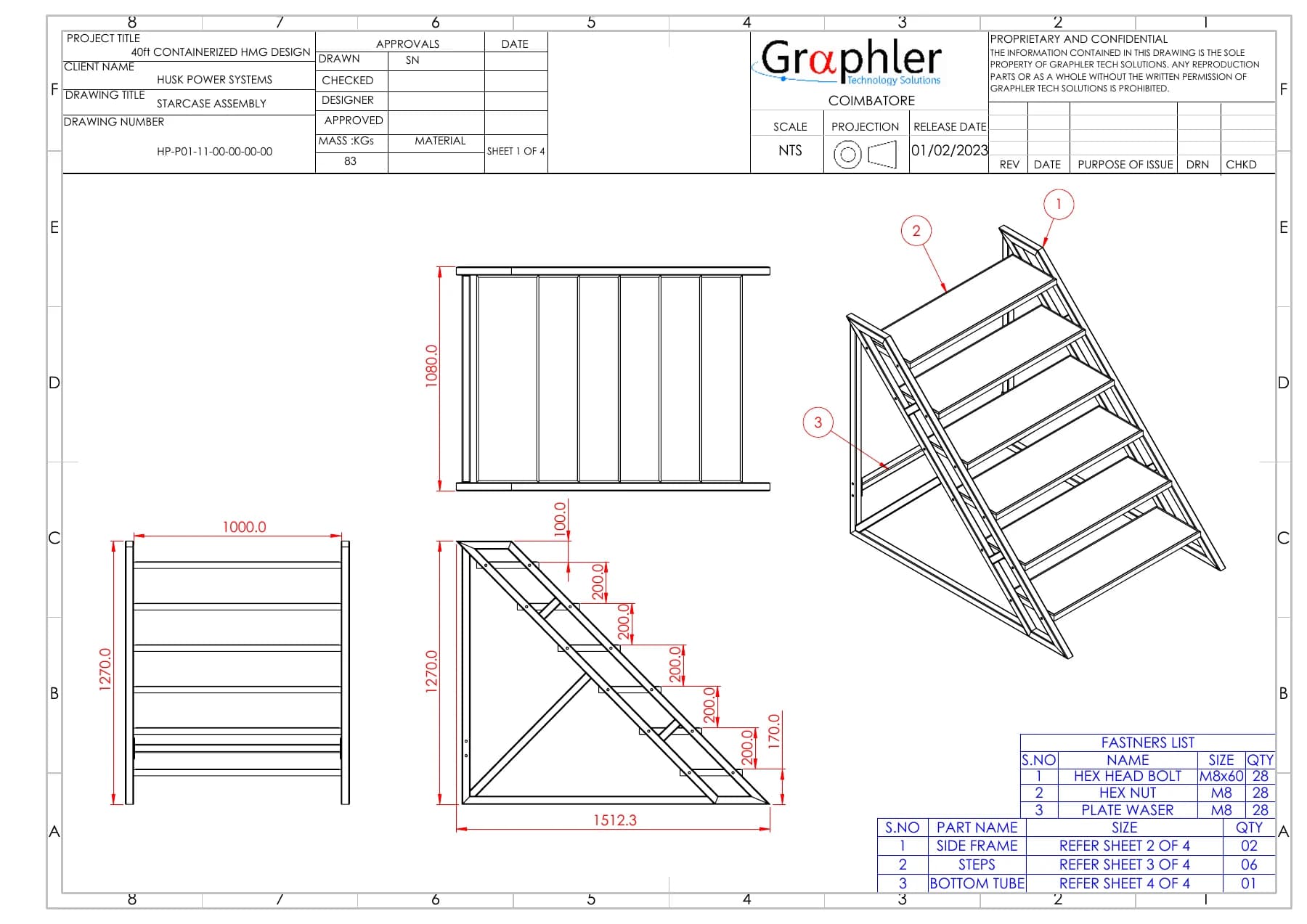
The staircase assembly provides the external access interface. The drawing package breaks the assembly down into components and fastening details
06 / Ducts and Cable Routes
Ventilation ducts and cable routes
Exhaust duct assembly
The duct drawing defines the route, branches, supports and local connection details. Its position links the battery and inverter zones to the exhaust path
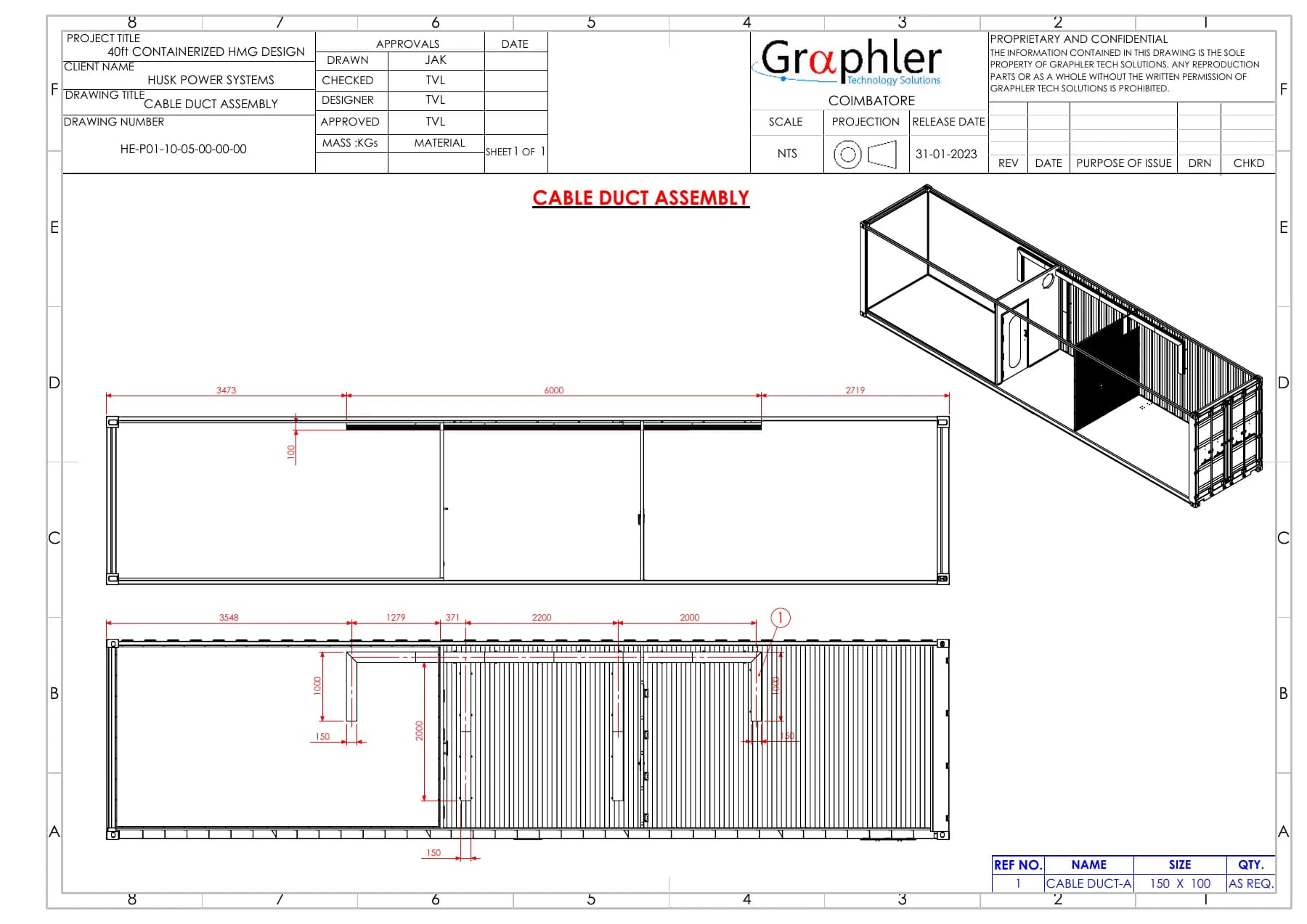
Cable duct assembly
The cable duct drawing establishes a separate service route within the container. This helps coordinate electrical connections with doors, partitions and equipment mounting
The internal assembly brings these details together with the main door, mesh doors, air-conditioning outdoor unit and panel rack. Together, these interfaces define the detailed container assembly
07 / Structural Analysis Setup
Module weight and wind-load definition
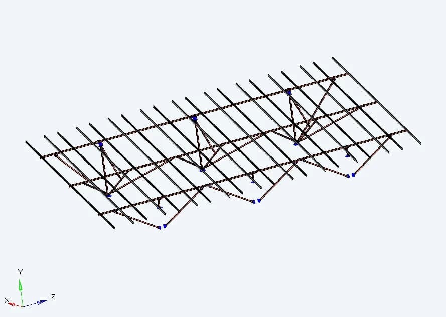
Mesh and member arrangement
The finite element model represents the solar-support frame and its connection regions. Local mesh views resolve the joints used to transfer forces between members
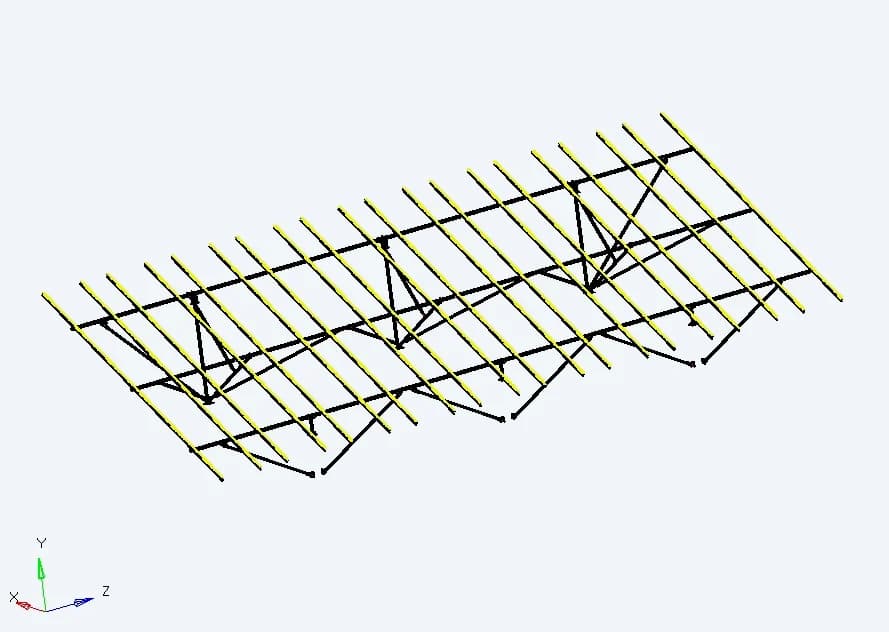
Wind-load application
The report combines self-weight with wind loading. Its module basis is 70 panels at 35 kg each, with a specified wind pressure of 1,500 Pa per panel
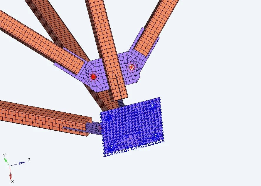
Connection-level representation
The local mesh shows the bracing and connection plates at a joint, supporting closer review of force transfer and concentrated stress
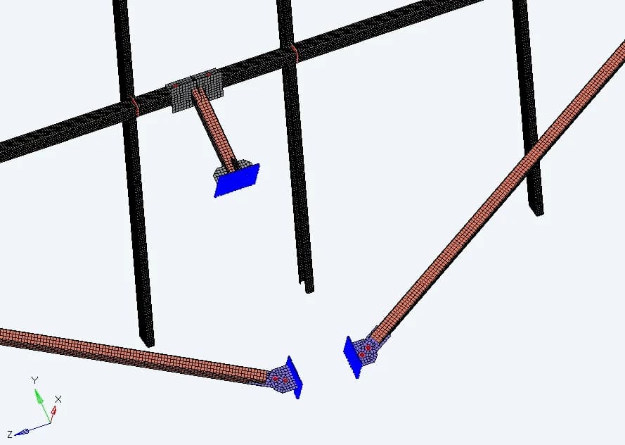
Model restraints
The restraint view identifies the fixed locations used in this analysis. Interpretation of the results depends on these support assumptions
Revised FEA material basis: steel density 7,850 kg/m³, elastic modulus 200 GPa, Poisson ratio 0.29 and yield strength 240 MPa
08 / Structural Response
Deflection and stress across the assembly
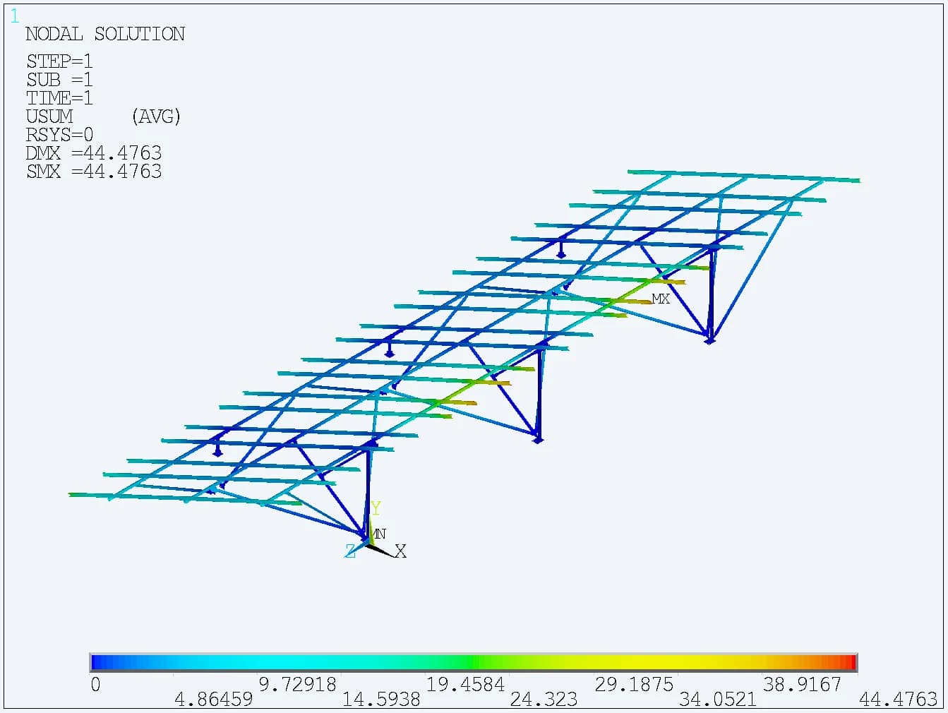
44.5 mm reported purlin deformation
The revised report identifies the purlin as the location of maximum deformation. The contour shows where the frame is most flexible under the analysed load case
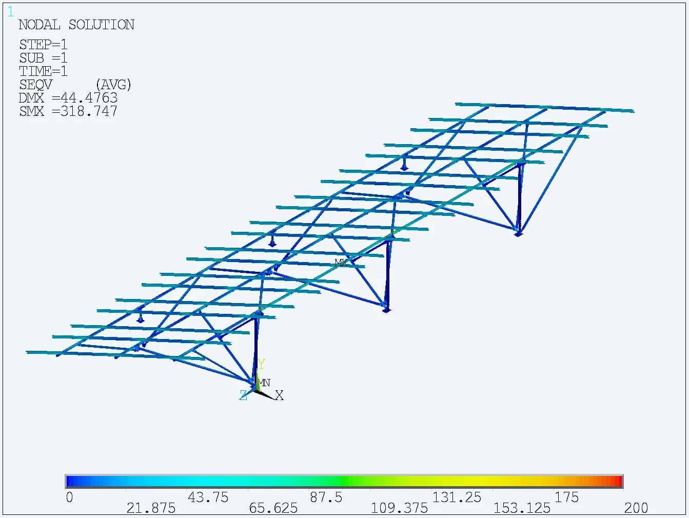
200 MPa displayed overall stress
The overall stress view provides a first reading of the frame response. Separate local views reveal concentrations that need interpretation at the connection level
Quoted results are from the July 2022 revised-thickness report. They describe that model and load case; a deformation acceptance limit is not stated in the supplied report
09 / Critical Structural Details
Stress concentrations at critical joints
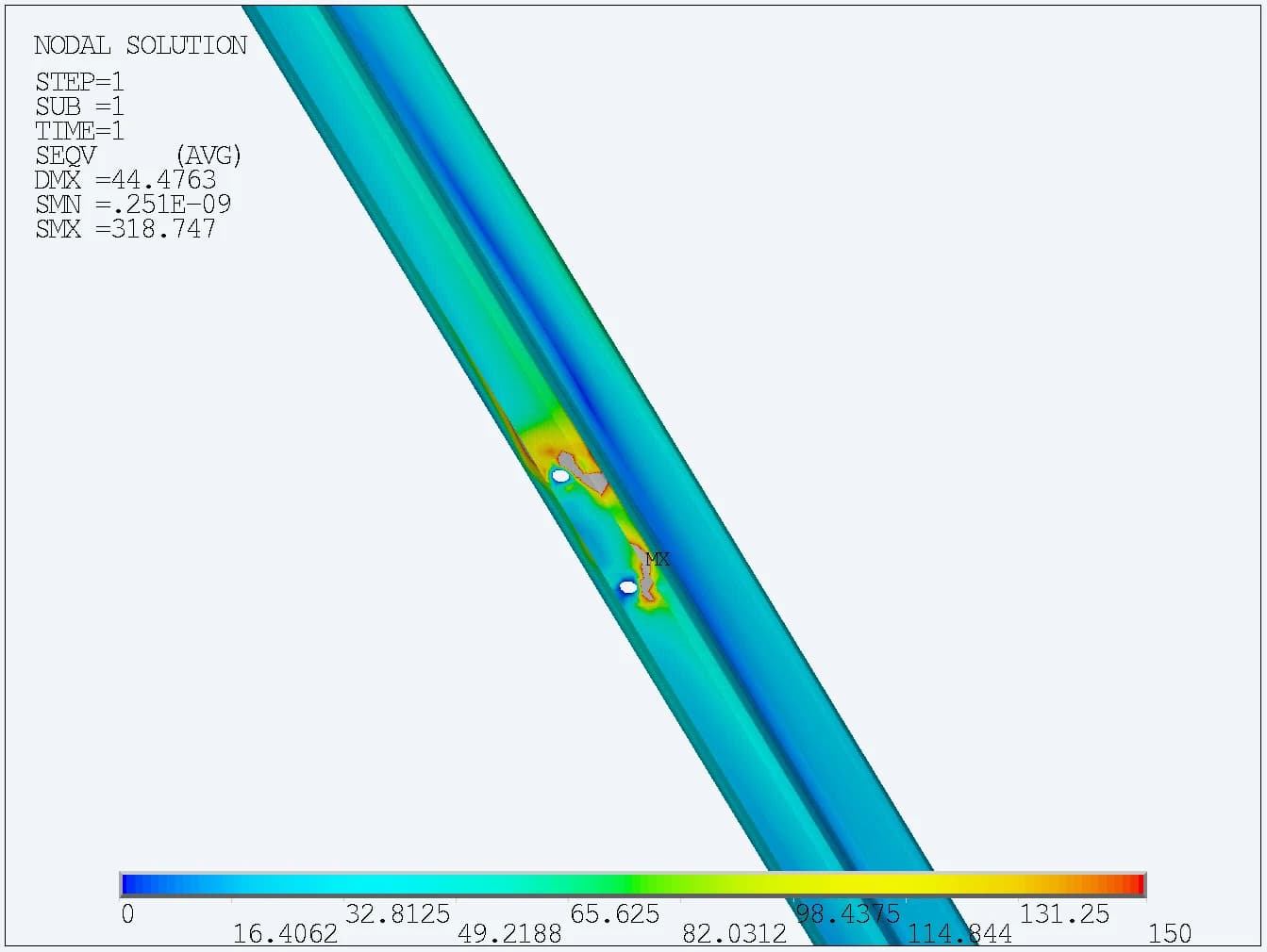
Purlin bolt-hole region
The report records a local peak of 318 MPa and discusses the influence of the washer. It uses 150 MPa as a representative value. This local peak requires joint-level interpretation
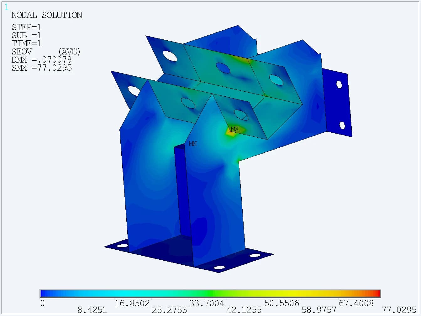
Corner-casting pivot
The revised report records 77 MPa at the pivot fixed to the ISO corner casting. A separate pivot-block and column-base-plate assessment records 18 MPa
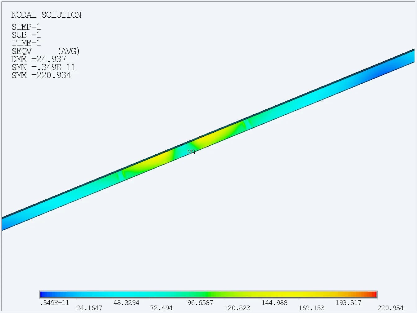
Rafter response
The source describes a 220 MPa peak as a singularity and gives 170 MPa as the representative maximum for the rafter
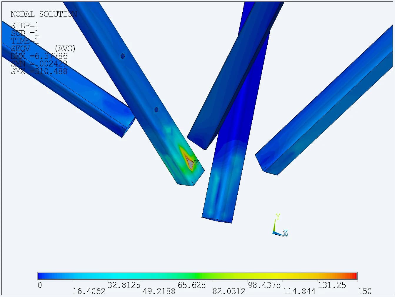
Bracing and weld region
The source gives 150 MPa as the representative bracing stress after discussing the peak at the gusset-to-column weld region
The reported interpretations are retained here as analysis findings. Local peaks, washer/contact effects and weld details need appropriate connection review before engineering acceptance
10 / Thermal and Ventilation Setup
A container model in hot ambient conditions
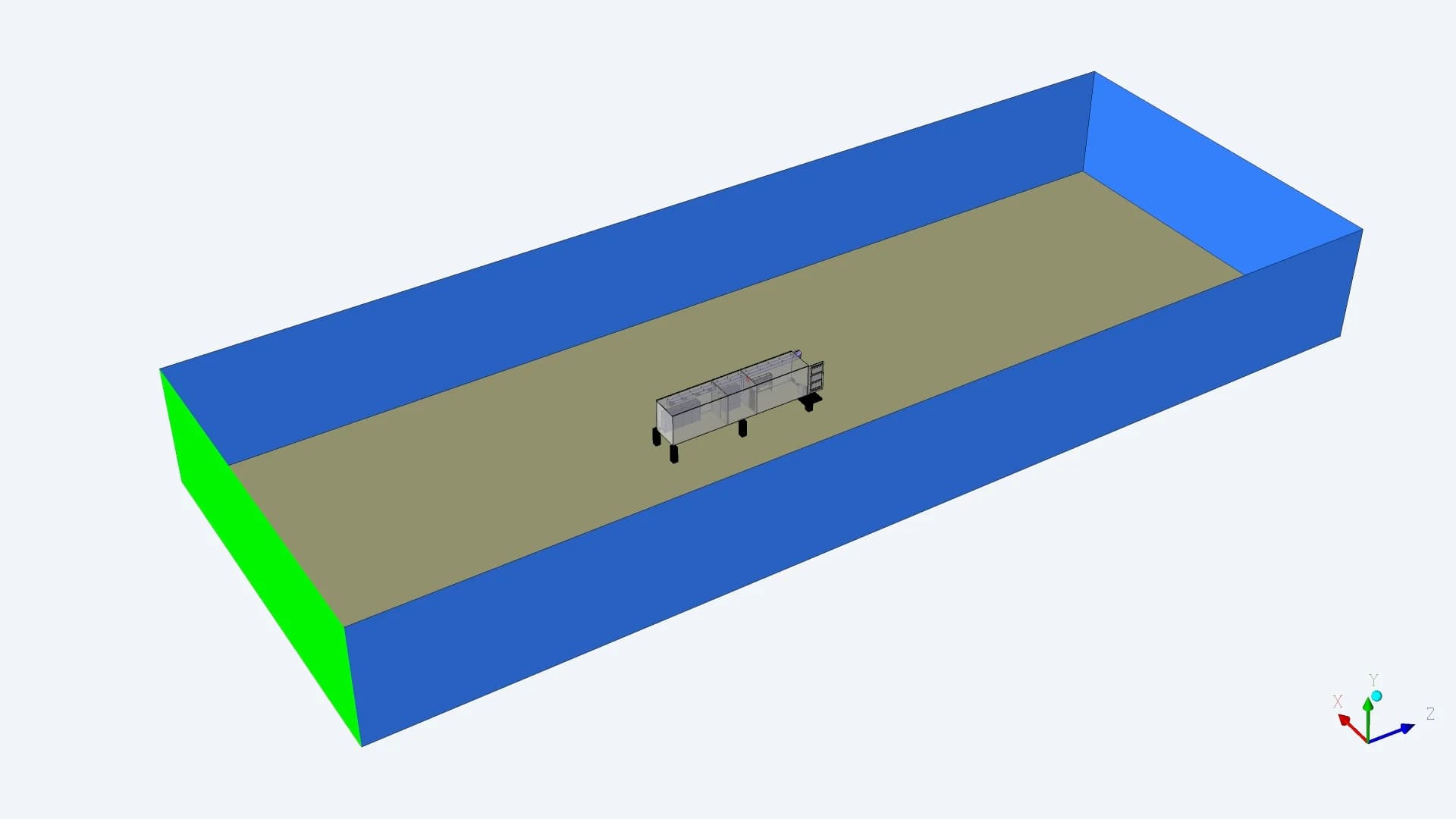
External flow domain
The CFD model places the elevated container inside a full-scale external domain. The boundary-condition presentation specifies wind approaching from opposite the container door
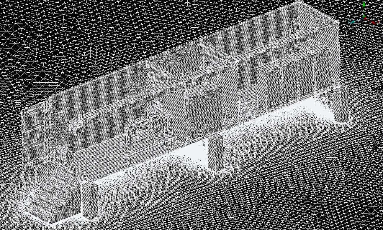
Container and local mesh
The mesh captures the surrounding air and the internal equipment arrangement. The proposed setup treats filters and mesh as porous regions based on their open area
| SIMULATION INPUT | SPECIFIED CASE |
|---|---|
| Ambient conditions | 45°C, 1 atm; 1 m/s external wind |
| Solar loading | 1,100 W/m² irradiation |
| Battery heat input | 3,750 W distributed across four battery racks |
| Inverter heat input | 8,000 W applied over the inverter volume |
| Analysis approach | Steady simulation; fan openings specified as interior |
These heat loads are modelling assumptions in the boundary-condition report. They are not product output ratings or verified operating efficiencies
11 / Flow Development
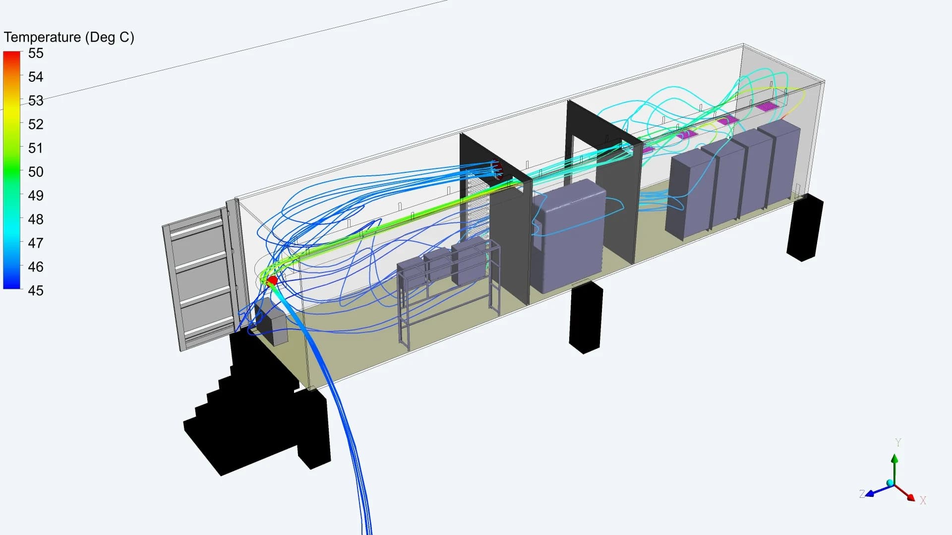
Airflow through the compartments and exhaust route
Streamlines make the route through the openings, partitions and equipment zones visible. The section views add a local picture of the flow, showing stronger velocity along the duct and uneven circulation within the occupied compartments
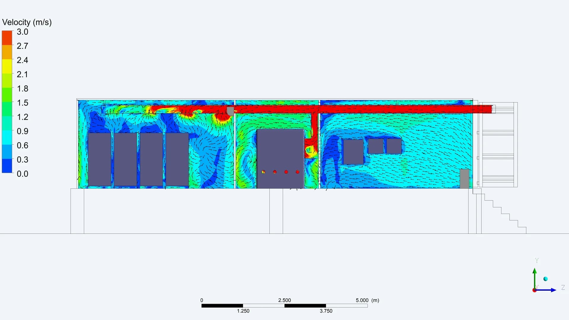
Velocity in an internal section
The velocity field helps identify the main flow path and regions with less air movement around the equipment
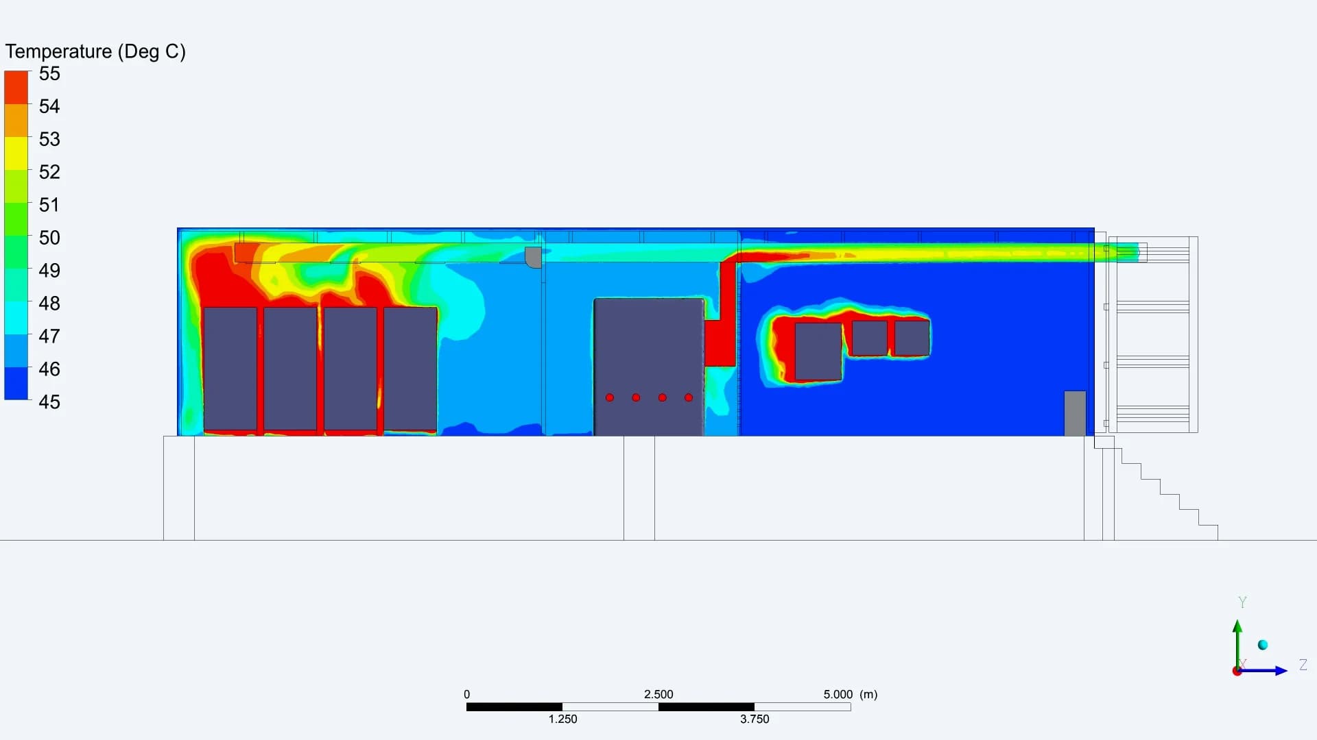
Temperature in the same section
The temperature field connects the airflow pattern to local heating. The source legend spans 45–55°C in this plotted plane
Original simulation plots retain their legends. Different figures use different ranges, so colours should be interpreted within each plot
12 / Equipment Temperature Review
Room-air and equipment-surface temperatures
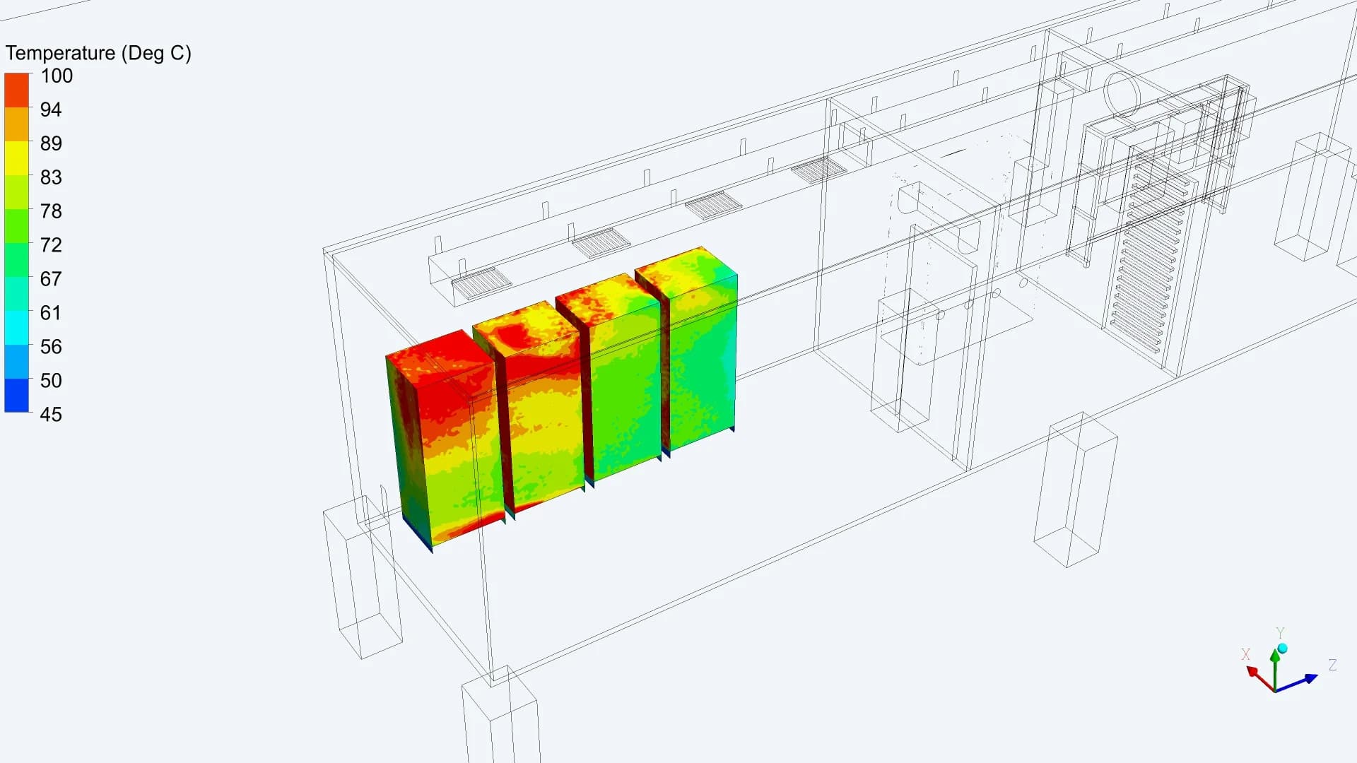
Battery surfaces
The battery contours show an uneven temperature distribution across the four racks. Area-weighted averages in the result file range from 58.0°C to 72.3°C
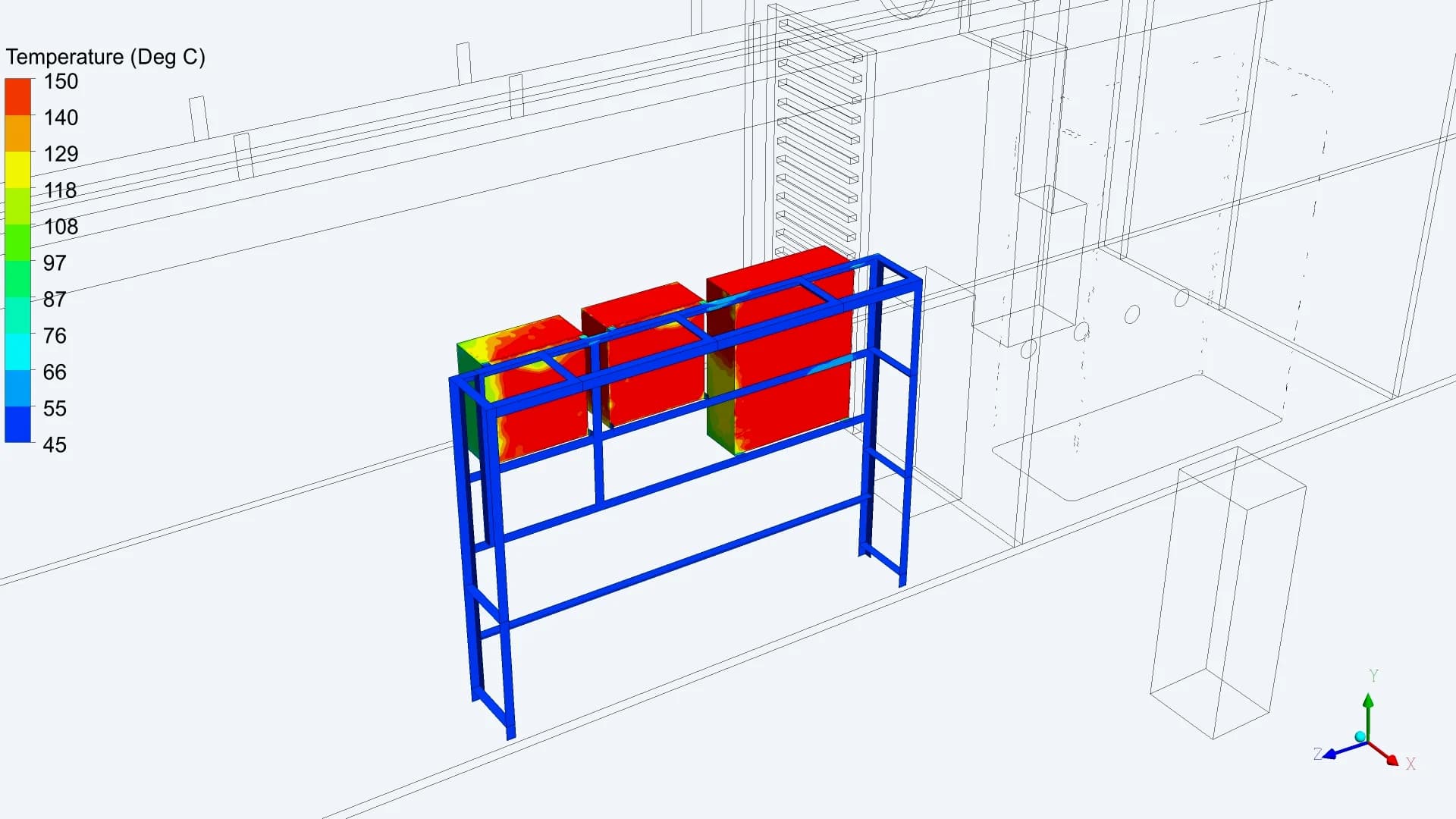
Electrical panel surfaces
The component plots highlight concentrated heating on the electrical panels. The result file reports a 90.2°C area-weighted average for the ACDB surface
| REGION / COMPONENT | REPORTED TEMPERATURE | AVERAGE TYPE |
|---|---|---|
| Battery-room air | 48.2°C | Volume average |
| Inverter-room air | 46.5°C | Volume average |
| Front-room air | 45.7°C | Volume average |
| Battery surfaces 1 / 2 / 3 / 4 | 67.8 / 72.3 / 69.1 / 58.0°C | Area-weighted surface |
| Inverter surface | 56.5°C | Area-weighted surface |
| ACDB surface | 90.2°C | Area-weighted surface |
| MJB1 / MJB2 surfaces | 77.8 / 67.3°C | Area-weighted surface |
Source: CASE-1 / Temp values.txt. Values rounded to one decimal. Surface averages are distinct from room-air averages and local contour maxima
The useful finding: average air temperature alone is insufficient
The component results identify where thermal review should focus, even when room-air averages remain closer to ambient. This gives the design team a basis for reviewing heat inputs, airflow paths and component temperature limits before acceptance
13 / Fabrication Documentation
Assembly drawings and fabrication details
The internal assembly sheet ties the individual subsystems to one coordinated arrangement. Dimensions, sections and item references link the enclosure and equipment supports to their associated drawing numbers
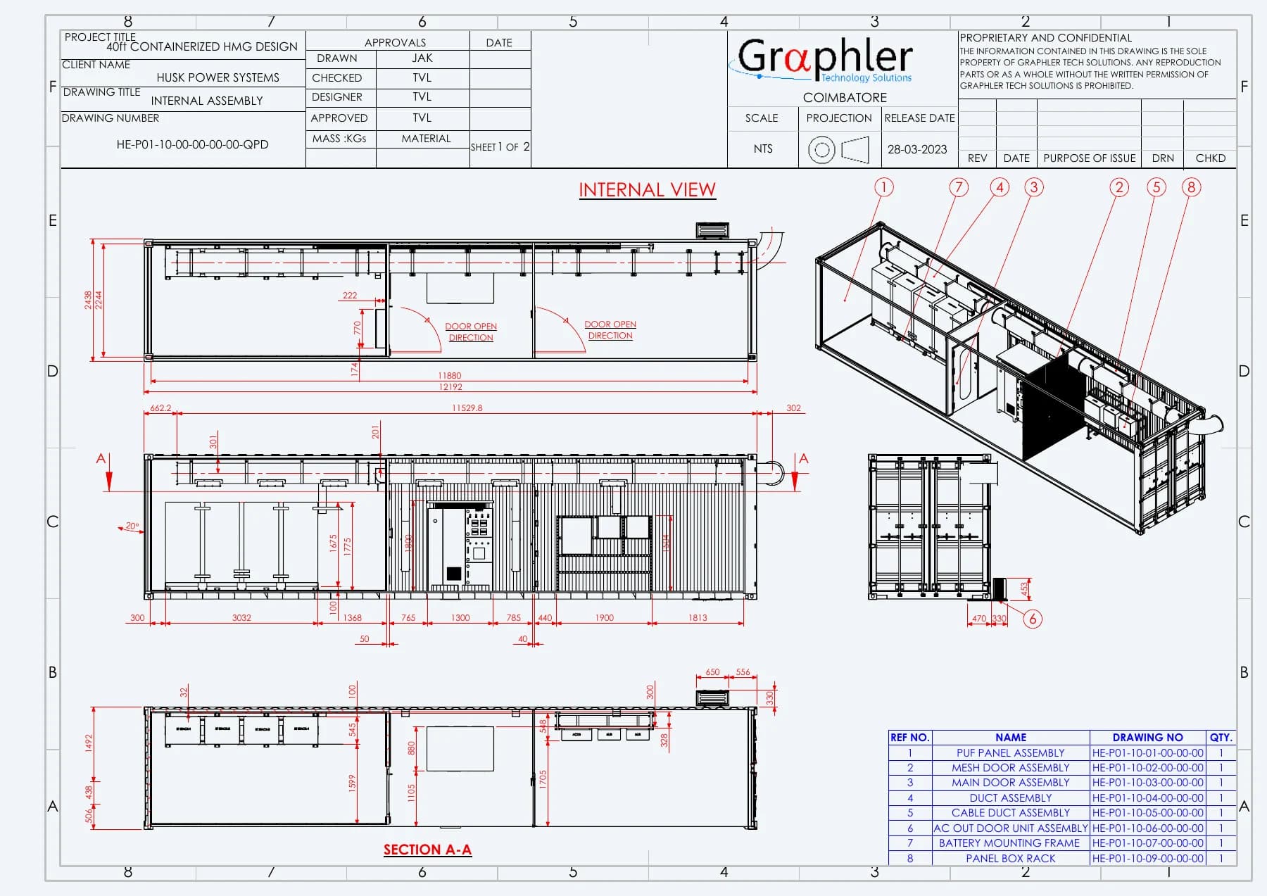
| PACKAGE | CONTENTS REPRESENTED IN THE ARCHIVE |
|---|---|
| Product arrangement | Concept revisions, 10° general arrangement and render views |
| Solar mounting structure | 10° and 25° assembly / component drawings and BOM workbooks |
| Container internal assemblies | Insulation, doors, ducts, battery mounting and panel rack |
| Access and service details | Staircase, ladder, cable ducts and AC mounting assembly |
| Engineering analysis | Original and revised FEA reports; CFD setup and case results |
The archive contains successive revisions. Drawing selection and issue status should follow the project document register when the package is used for manufacturing
Project Outcome
A coordinated product design with documented analysis
Step 01: Defined product architecture
Container zoning, equipment integration and the solar-support arrangement are captured in the design records
Step 02: Analysis findings for review
Structural contours identify member and joint response. CFD results identify airflow patterns and thermal concentrations
Step 03: Detailed engineering package
Assembly drawings, component details and BOMs connect the developed design to fabrication planning
One product, coordinated in detail
The work connects the visible product to the engineering beneath it: the supporting structure, internal arrangement, analysis findings and manufacturing documentation The documented outcome covers design and analysis deliverables. The supplied archive does not establish final thermal acceptance, commissioning or measured field performance