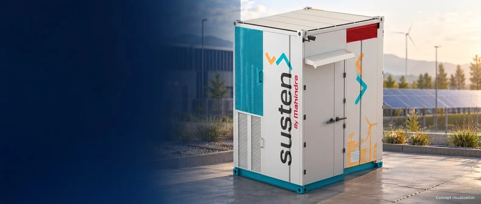
Mahindra Susten GEN-E Container
We developed the BESS enclosure through mechanical design, engineering analysis and fabrication support.
Container Design and Development
BESS
- Requirement
A compact energy-storage unit
House batteries, power-conversion equipment and a transformer within a 12-foot enclosure. Provide cooling, service access and space for electrical and fire-system interfaces.
- Challenge
Equipment, heat and structure
Accommodate equipment loads, separate thermal zones and lifting provisions. Coordinate partitions, ducts and mounting details with the access and fabrication requirements.
- Deliverables
Design through fabrication support
Our work covered concept studies, detailed CAD, structural FEA and thermal CFD, fabrication drawings and BOM records, followed by support for workshop integration and design revisions.
- Nominal container length
- 12 ft
- Structural analysis programme
- 6 load cases
- Thermal simulation input
- 50°C ambient
Development Programme
The engineering process

Step 01: Define
Equipment requirements, envelope, access & heat loads

Step 02: Explore
Module studies and alternative container arrangements

Step 03: Integrate
Structure, partitions, equipment and service interfaces

Step 04: Evaluate
Structural load cases, airflow & temperature distribution

Step 05: Detail & support
Drawings, BOMs, workshop feedback and revisions
Concept Development
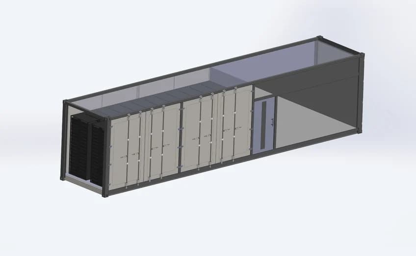
The compact enclosure & it’s internal arrangement
BESS - Design/Development
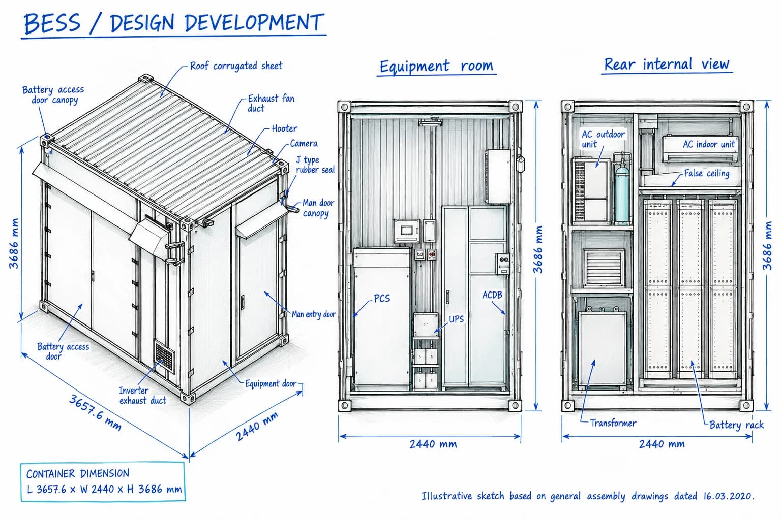
Illustrative sketch based on the 16 March 2020 general assembly drawings Overall dimension lines: 3657.6 × 2440 × 3686 mm
Early Design Studies
The ideas behind the container layout
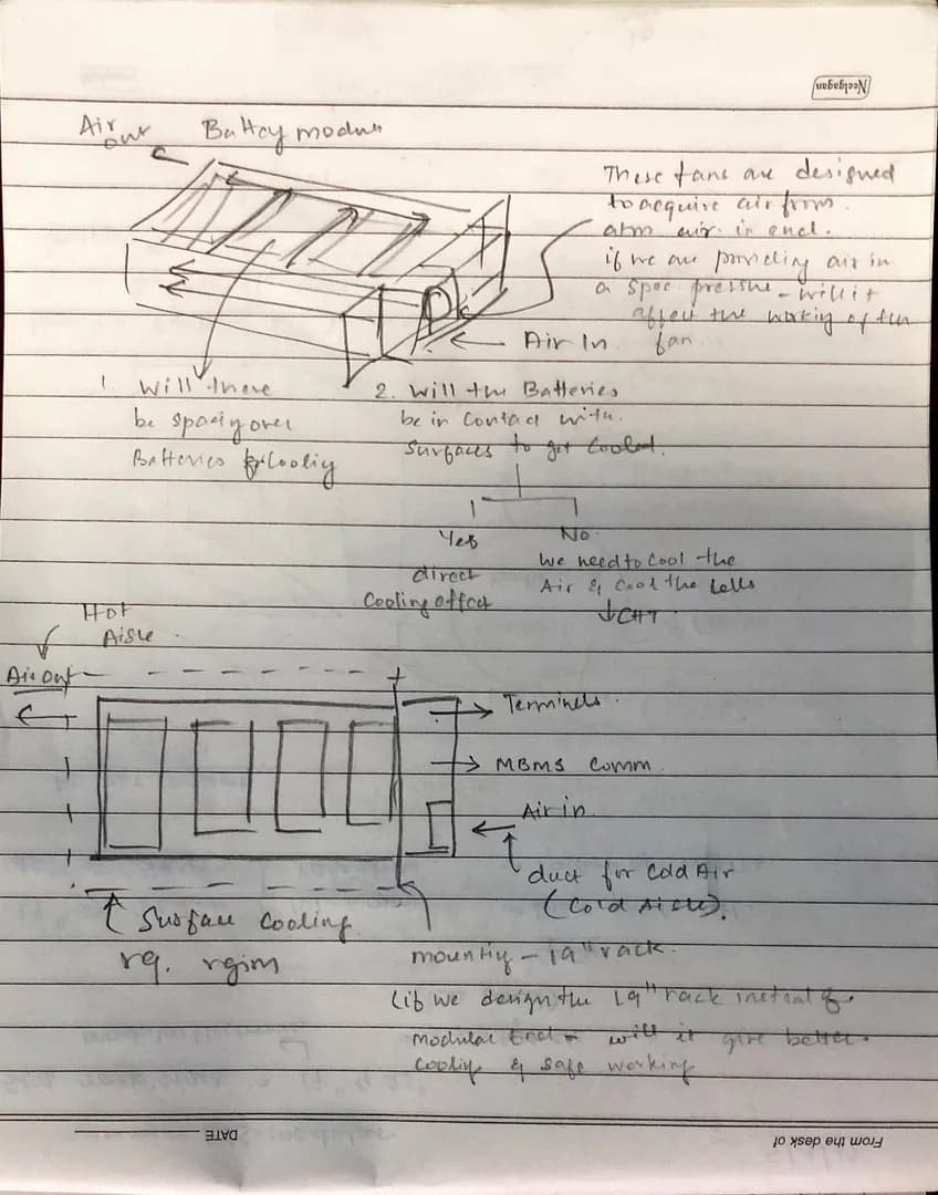
Initial concept notes
5 Essential UX Principles for Intuitive Product Design
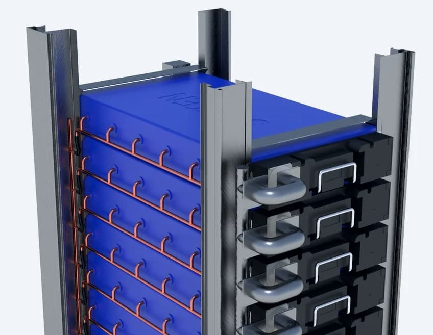
Module and cooling studies
FE Analysis to validate the structural frame
Container alternatives
FE Analysis to validate the structural frame
Space Planning
Separate spaces for equipment and thermal control
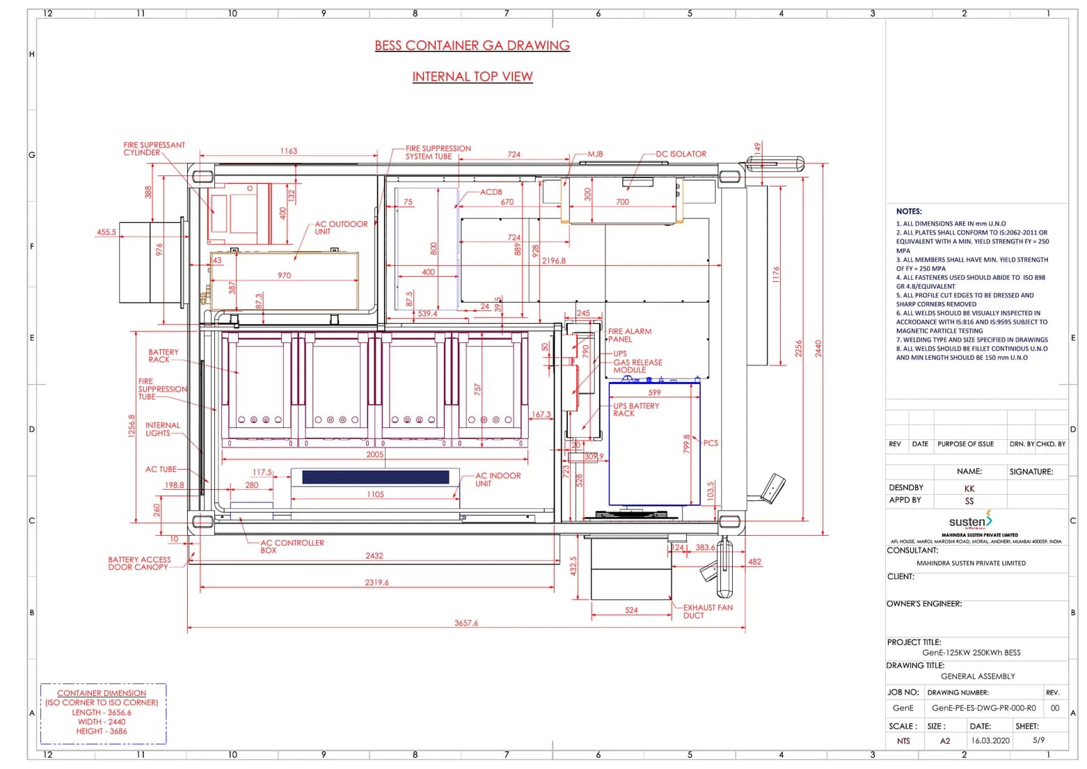
The general arrangement defines the equipment positions, access clearances and service routes.
Battery Room
Insulated space with battery racks, air conditioning and a false ceiling
Equipment Room
PCS, ACDB, UPS and control equipment share a dedicated service area
Rear service compartments
The drawings place the outdoor AC unit and suppression cylinder above the transformer compartment
Mechanical Development
The structure and its internal assemblies
01 Base Frame & Super Structure
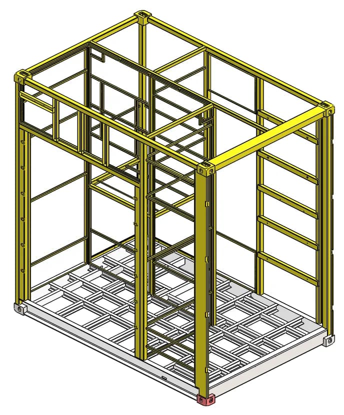
Original project CAD
We arranged the steel members around the equipment load paths. Corner fittings, frame connections and equipment supports form the structural basis of the enclosure
02 Insulations & Partitions
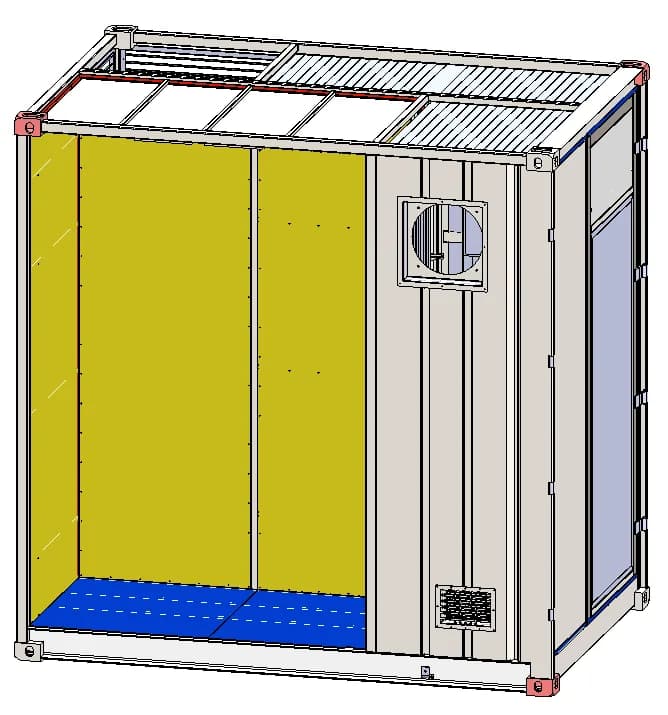
Original project CAD
Internal partitions separate the functional zones. Rockwool insulation and wall linings support thermal separation while accommodating the room layout and service openings.
03 Battery Room & False Ceiling
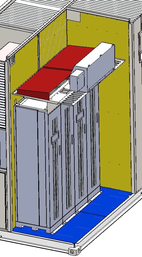
Original project CAD
The battery-room design coordinates rack access with the indoor AC unit and false ceiling. The ceiling arrangement manages supply and return airflow around the racks
04 Equipment & Service Access
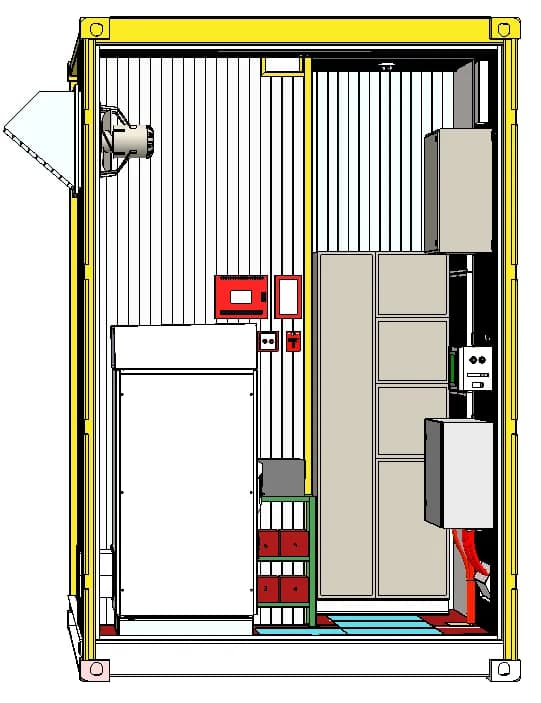
Original project CAD
The equipment room brings the PCS, UPS rack and electrical panels into a serviceable arrangement. Mounting details and access space developed alongside the main enclosure
Equipment Integration
The interfaces that make the enclosure work
05 Ventilation and weather hoods
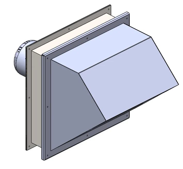
Original ventilation detail
Fan openings and external hoods coordinate exhaust flow with the enclosure wall. Louvres, filters and rain protection form part of the air path
06 Local cooling for the UPS rack
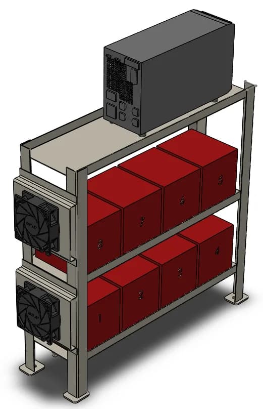
Original equipment detail
The UPS rack detail incorporates local fans around the equipment. This brings the cooling provisions into the mechanical arrangement
07 Fire-system routing
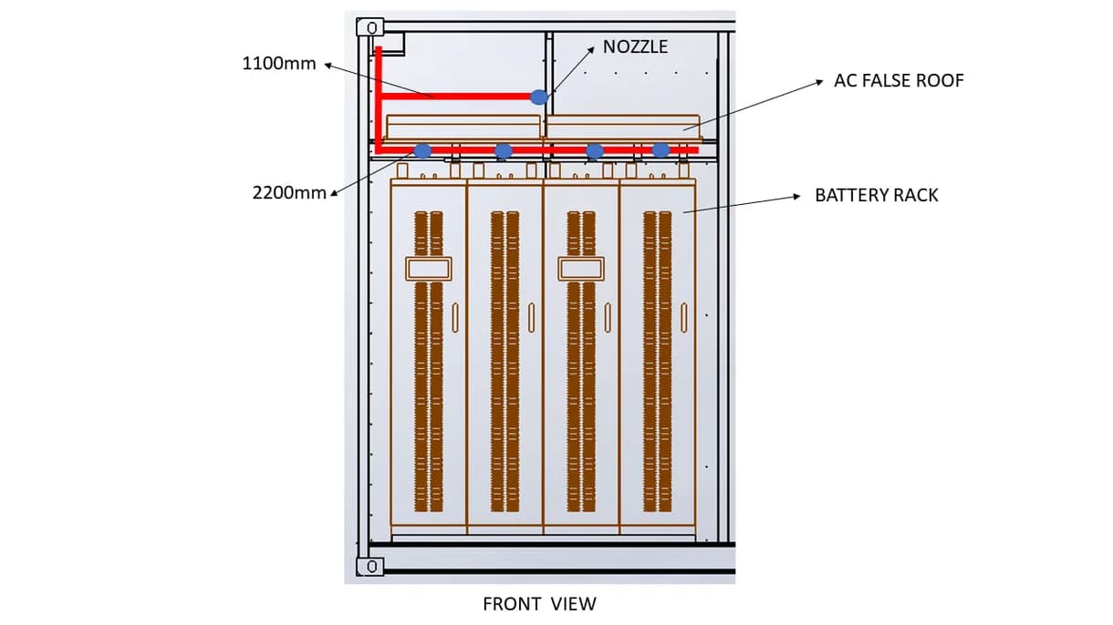
Original piping arrangement, October 2020
We coordinated pipe routes and nozzle positions with the battery racks and ceiling. The design reserves space for the cylinder and associated system interfaces
08 Cable routes and floor access
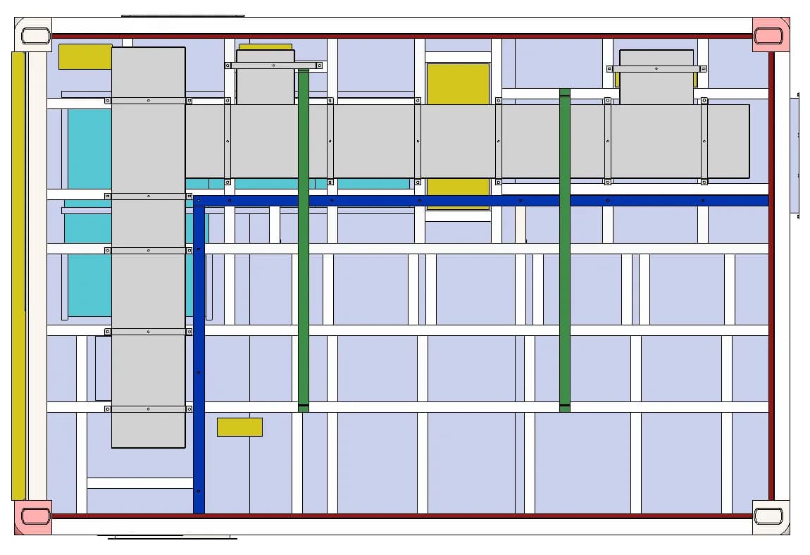
Original cable-tray plan
Underfloor trays organise the cable paths between equipment zones. Floor covers and gland interfaces provide access for installation and later service
Structural Analysis
The model, supports and applied loads
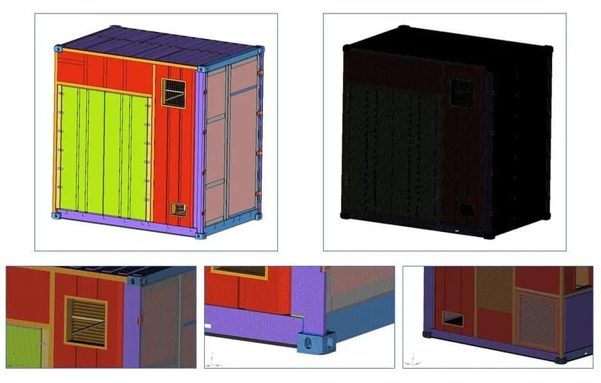
CAD idealisation and mesh
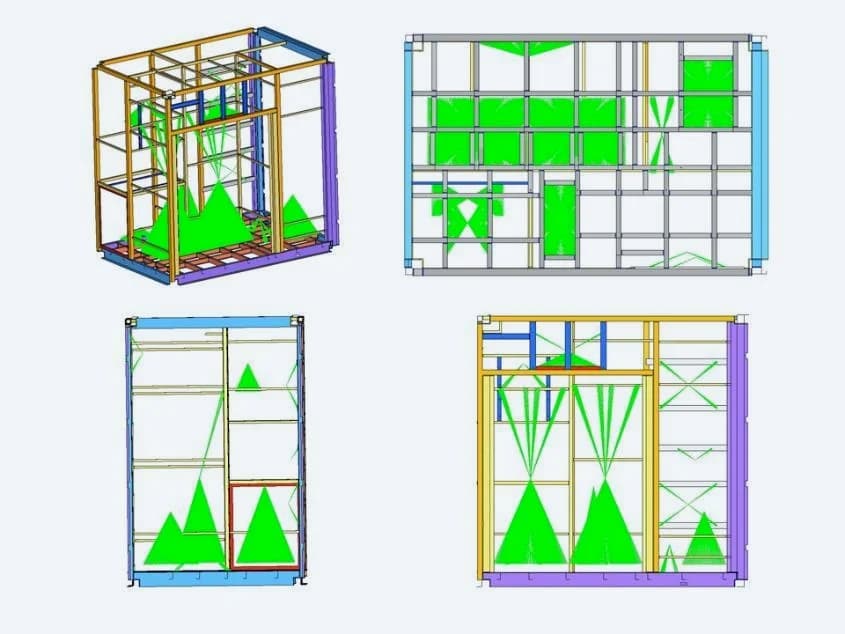
Equipment masses and mounts
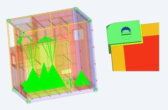
ISO-corner lifting restraints
Reports
Loading Conditions
| CASE | LOADING CONDITION | ASSESSMENT FOCUS |
|---|---|---|
| 01 | Self-weight + payload + 0.5 kN/m² walkway load | Equipment support and walkway response |
| 02 | Self-weight + payload + floor / roof live loads | Floor 2.5 kN/m², roof 0.75 kN/m² |
| 03 | Loaded bottom lifting | Four bottom ISO corners |
| 04 | Loaded top lifting | Four top ISO corners |
| 05 | Longitudinal wind + payload | External-flow pressures at 150 km/h |
| 06 | Transverse wind + payload | External-flow pressures at 150 km/h |
Structural Response
Deformation and Stress on a Component Level
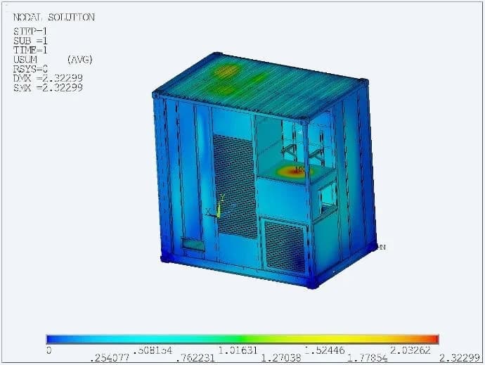
2.32 mm maximum displacement
The self-weight, payload and floor/roof live-load case shows the assembly response under the stated loading assumptions
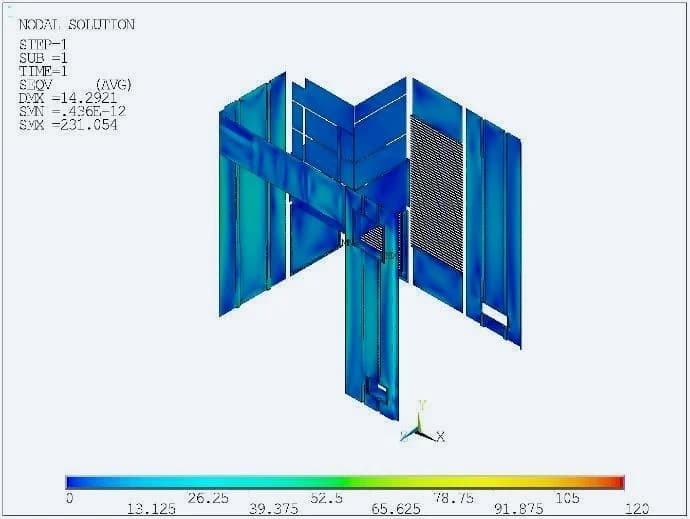
Wall-panel stress under wind
The transverse-wind plot displays a 120 MPa colour-scale cap. Its annotated maximum is approximately 231 MPa. Local peaks and broader panel response need separate interpretation
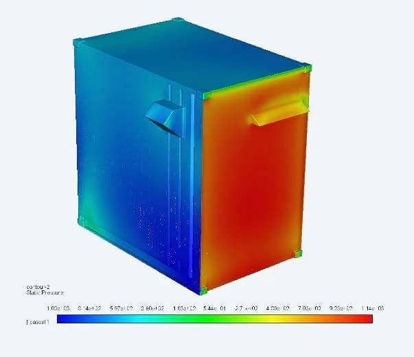
CFD pressures inform the wind cases
The external-flow study supplies pressure distributions at 150 km/h. The structural report records whole-assembly peaks of 379 MPa longitudinally and 307 MPa transversely, against a 240 MPa yield input These local peaks require further assessment. The report does not establish an unconditional pass for all wind results
Thermal and Flow Analysis
The airflow model and operating assumptions
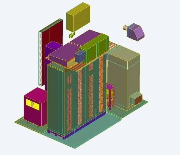
Simplified equipment and enclosure geometry
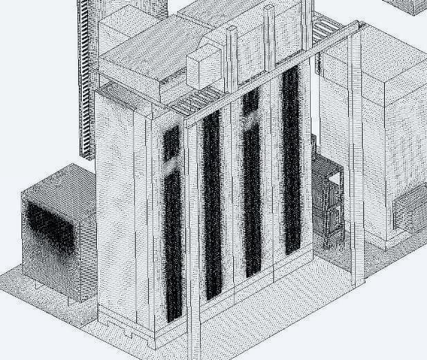
1.6 million surface elements / 14 million volume cells
| MODEL INPUT | SPECIFIED CONDITION | PURPOSE |
|---|---|---|
| Outdoor environment | 50°C ambient | External thermal boundary |
| Battery-room AC supply | 15°C at 1,177 CFM | Conditioned air to the battery zone |
| PCS airflow | 560 CFM | Power-conversion equipment airflow |
| Equipment-room exhaust | 675 CFM | Ventilation of the equipment zone |
| Transformer exhaust | 60 CFM | Ventilation of the transformer compartment |
The steady-state conjugate heat-transfer study includes conduction, convection and radiation. Equipment heat loads and external thermal effects define the simulation basis
Thermal Results
Temperature distribution and airflow
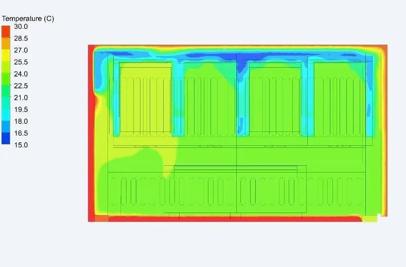
Battery room: 22.4°C average
The study reports average room air at 22.4°C and a maximum battery-rack temperature of approximately 26°C with the specified AC supply
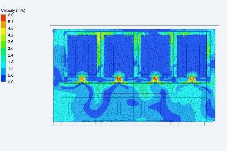
Airflow through the battery space
Velocity plots show how air travels through the room. They support review of the ceiling, rack clearances and supply/return arrangement
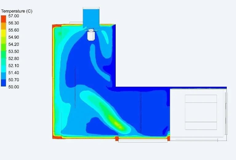
Equipment room: 52°C average
At a 50°C ambient boundary, the equipment-room study reports a 52°C average and a 62°C maximum room temperature
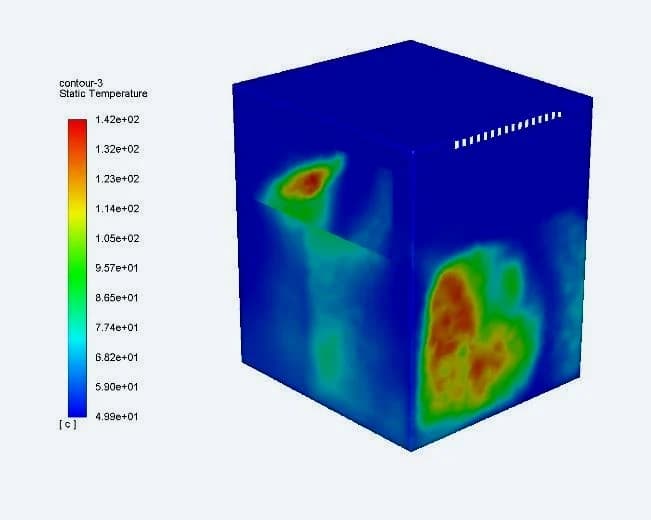
Transformer: 141°C surface peak
The report identifies heat accumulation at the transformer enclosure. It also reports average transformer-room air at 78°C
A specific finding for engineering review
The transformer hotspot needs further review of heat removal and the model assumptions. These values describe simulated conditions, with room-air and enclosure-surface temperatures identified separately
Fabrication Documentation
The details needed for manufacture
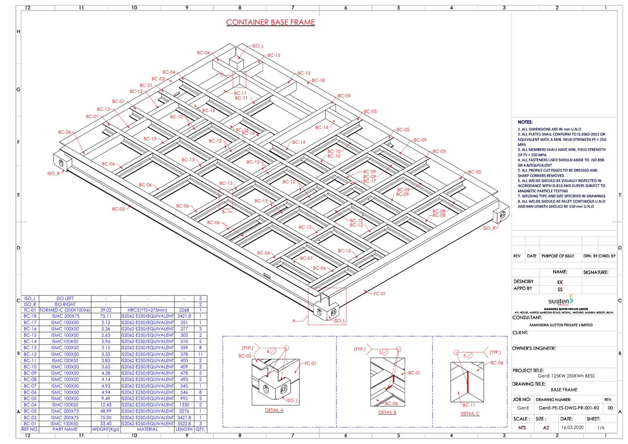
Structural fabrication package
Assembly drawings define member positions, sections, dimensions and weld requirements. The BOM identifies components for the mechanical package
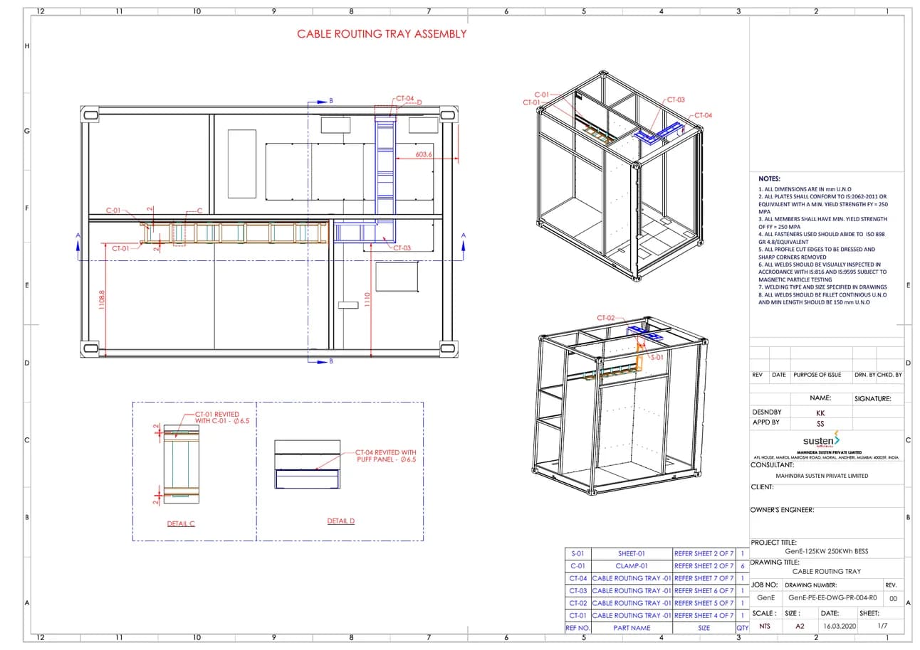
Service assemblies and interfaces
Detailed drawings carry the cable tray, hoods, floor covers and equipment fixings into fabrication. They connect the overall arrangement to individual parts
Workshop Support
The design progressed into fabrication
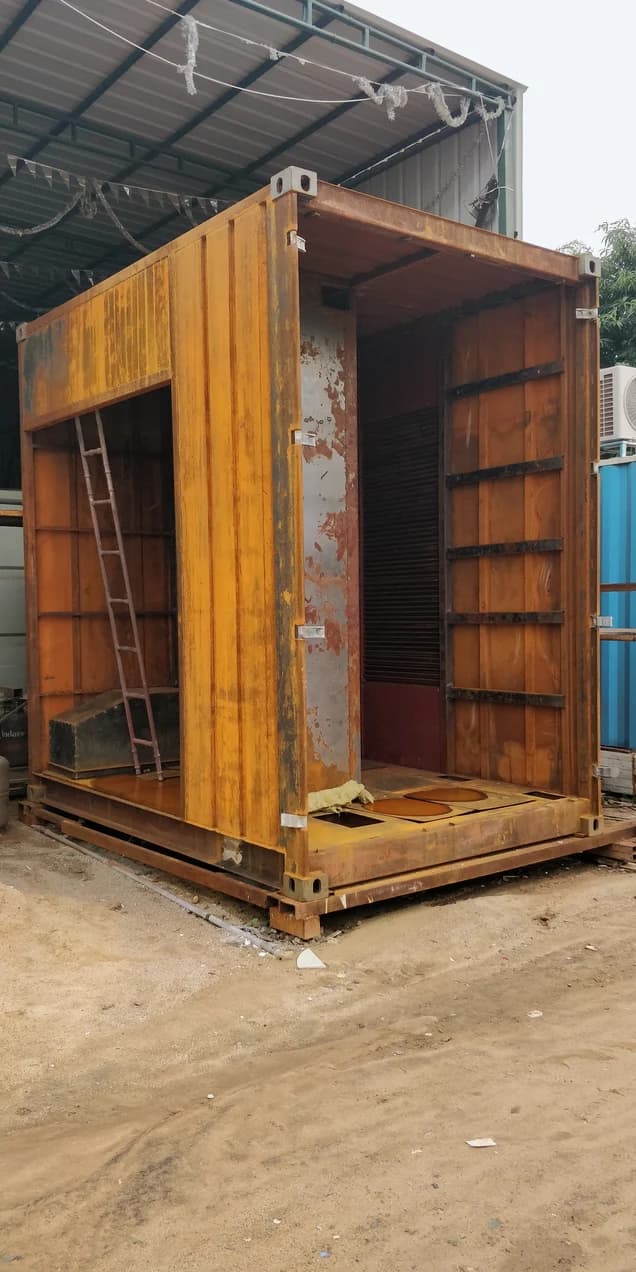
Enclosure fabrication
The October 2020 workshop records show the enclosure structure and sheet-metal integration. GTS supplied 3D views and cutout positions to support assembly
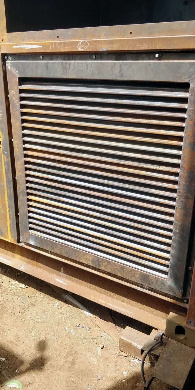
Openings and access
The team coordinated louvre and fan openings on site. The PCS flange changed from a C to a Z profile to improve fastening access
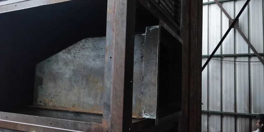
Hood and flange integration
Workshop feedback identified limited bolt access at the transformer hood. The team recorded a field welding solution and a flange change for a later iteration
Design Refinement
Revisions continued after workshop integration
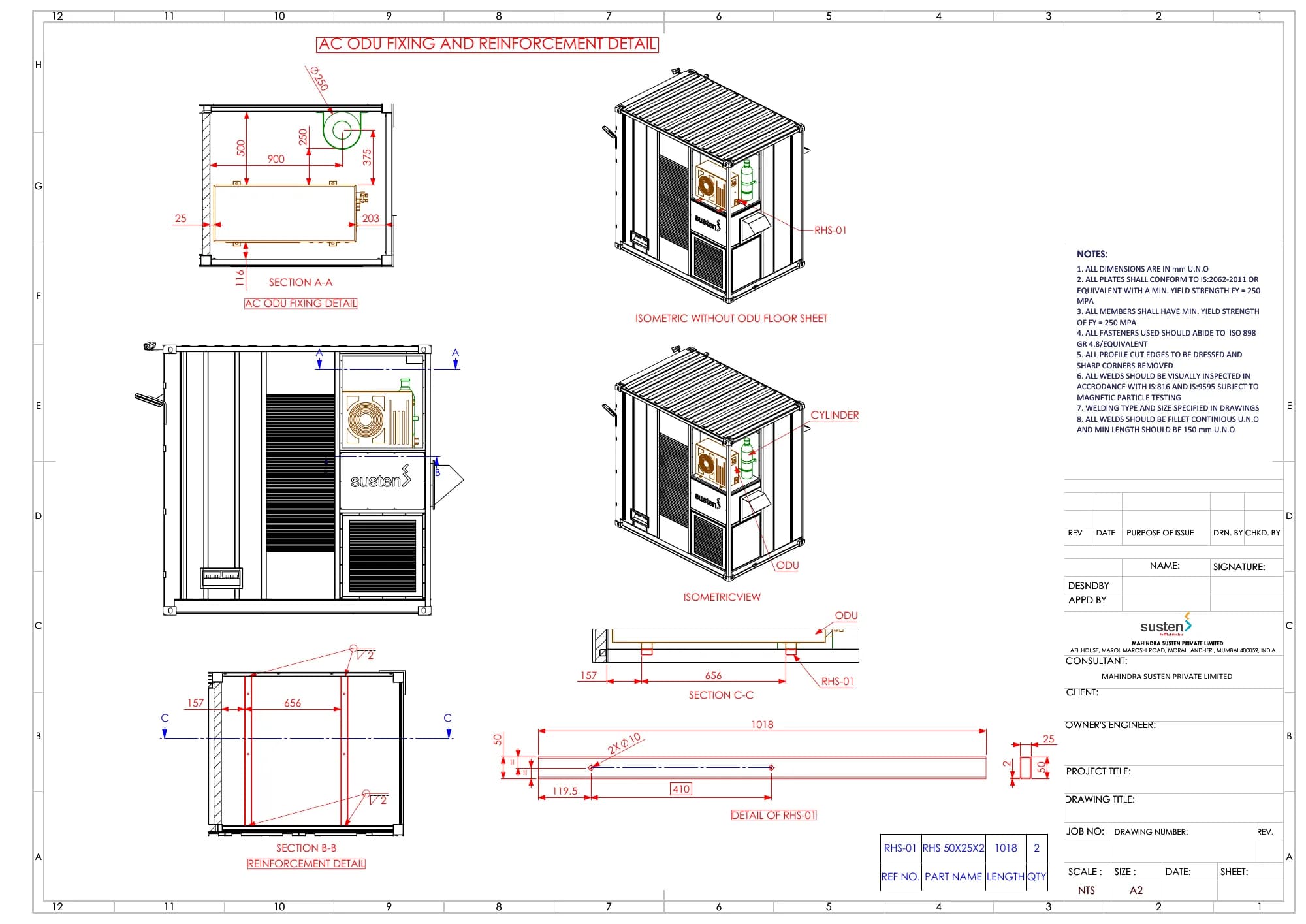
A November 2020 drawing records revised outdoor-unit and suppression-cylinder fixings with reinforcement details. The project history carries the design beyond its initial CAD release.
Documented Outcome
A coordinated enclosure design and physical build
Design information that supported the build
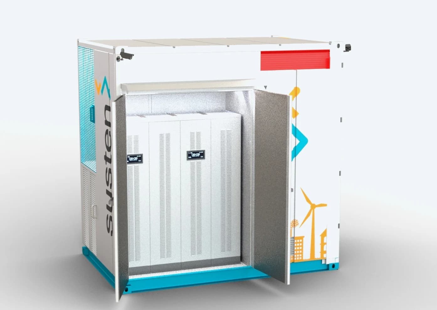
The project brought equipment packaging, enclosure design and engineering analysis into one mechanical development package. Fabrication drawings and workshop feedback supported physical integration
Original project render showing the intended battery-access arrangement
Engineering carried through to fabrication
The mechanical package supported fabrication and equipment integration. CAD and drawings established the build information, while FEA and CFD identified structural and thermal responses for engineering review