20 Ton Lifting Frame
Our work for Bradken India brought the lifting requirement into a defined frame geometry, structural analysis and detailed fabrication documentation.
Design and Development
20 Ton Lifting Frame
- Requirement
A 20-ton Lifting Frame
Bradken India needed an engineered frame for a 20-ton lifting application, supported by a structural assessment and drawings for fabrication
- Challenge
A Defined Load Path
Designing a lifting frame capable of safely handling loads up to 20 tons requires careful consideration of structural integrity, load distribution, liftingpoint configuration, and operational stability. The frame needed to withstand demanding lifting conditions
- Deliverables
The Engineering We Delivered
Our work covered the 3D assembly, detailed component and weld drawings, a bill of materials and a structural FEA report
- Operating Load
- 20t
- Frame Footprint
- 5 x 5m
- Lifting Lug Assemblies
- 4
The Development Process
01 Concept Sketch
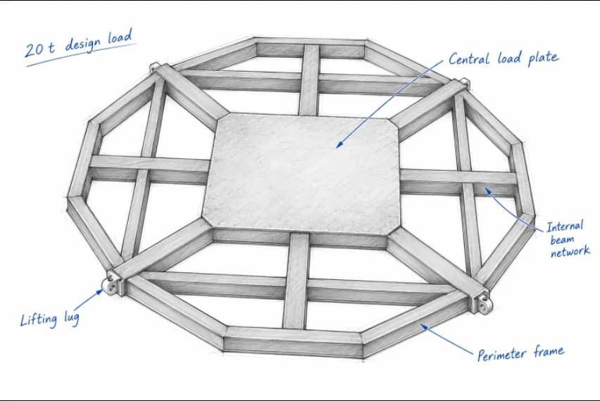
Illustrative reconstruction based on the project geometry
We organised the concept around the central load area, supporting beams and lifting locations. The annotations explain how these parts work together.
02 CAD Assembly
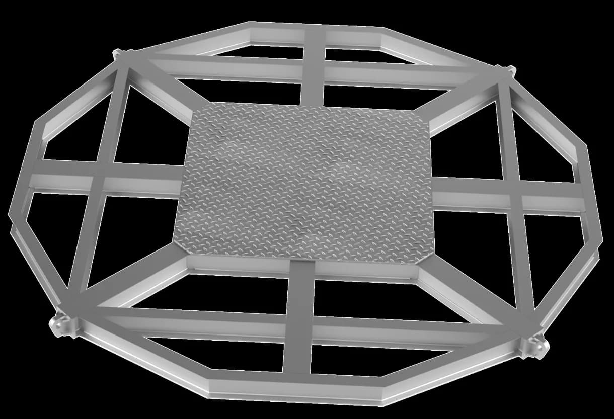
CAD visualisation of the complete frame
We brought the perimeter, internal beam network, top plate and four lifting lugs into one CAD assembly to define the frame geometry.
03 Detailed CAD
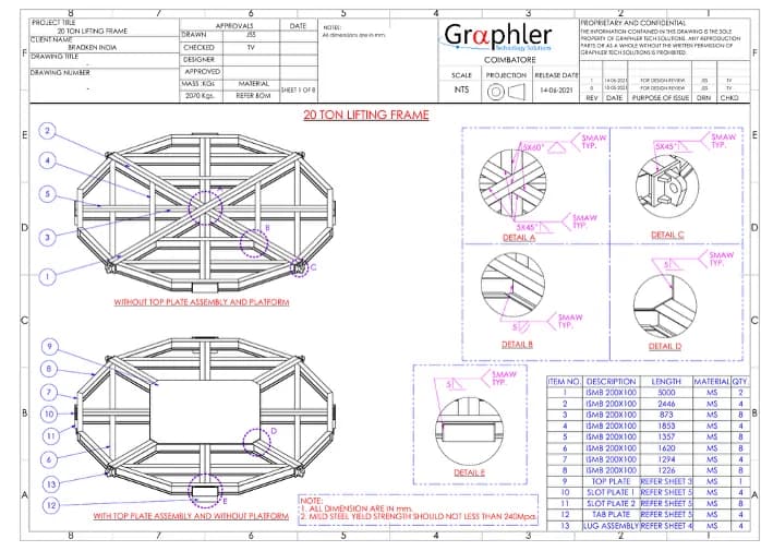
Assembly drawing with weld details and BOM
We defined beam sections, plate sizes, lug geometry and weld details. The drawings and BOM translate the model into information for fabrication.
04 FEA Validation
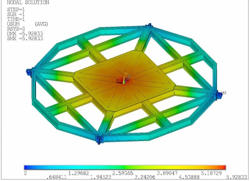
Total deformation contour at the 20 t operating load
We checked the frame under the documented 20 t load case using static FEA. A separate 40 t case examined its response under a higher load. 5.9 mm deformation 118 MPa stress*
05 The Physical Frame
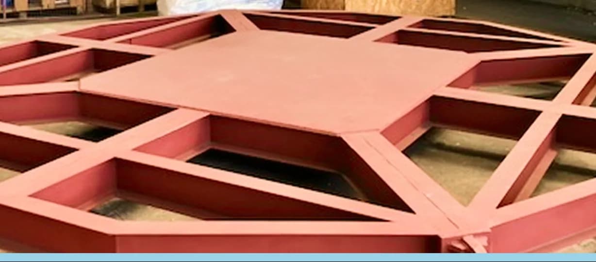
The design takes physical form
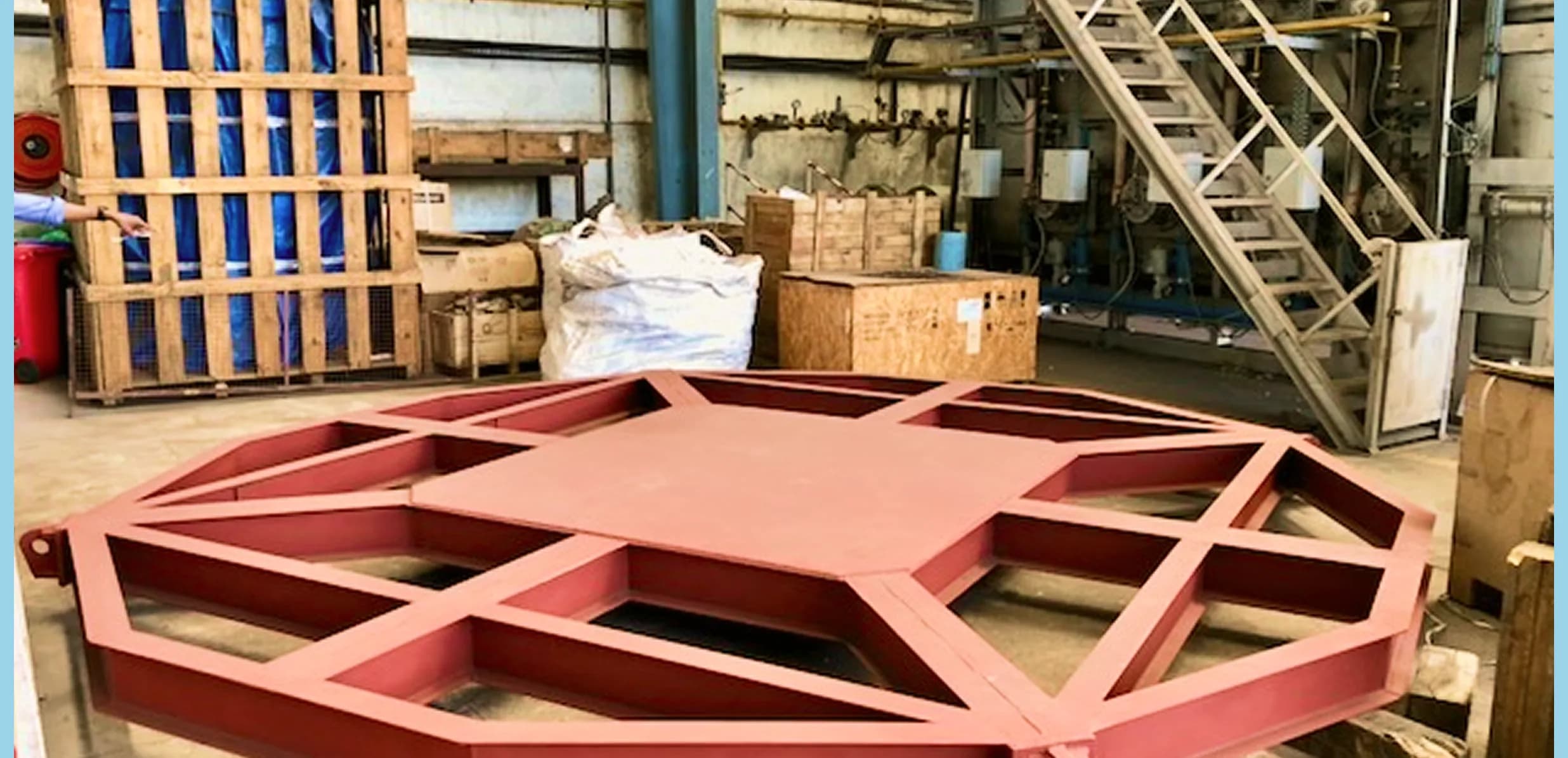
The workshop photograph shows the frame in physical form, with the central plate and beam arrangement developed in the design.
A clear basis for fabrication
The work connected the lifting requirement to a defined steel structure and a documented structural assessment. Detailed drawings gave the fabrication team the member, plate and connection information needed to plan the build.